

Rim, hub and manufacturing method of hub
A manufacturing method and rim technology, applied in the direction of wheel manufacturing, rims, manufacturing tools, etc., can solve the problems of poor running stability and poor anti-fatigue ability, and achieve the effect of stable running, enhanced anti-fatigue ability, and huge market application potential.
- Summary
- Abstract
- Description
- Claims
- Application Information
AI Technical Summary
Problems solved by technology
Method used
Image

Examples
Embodiment 1
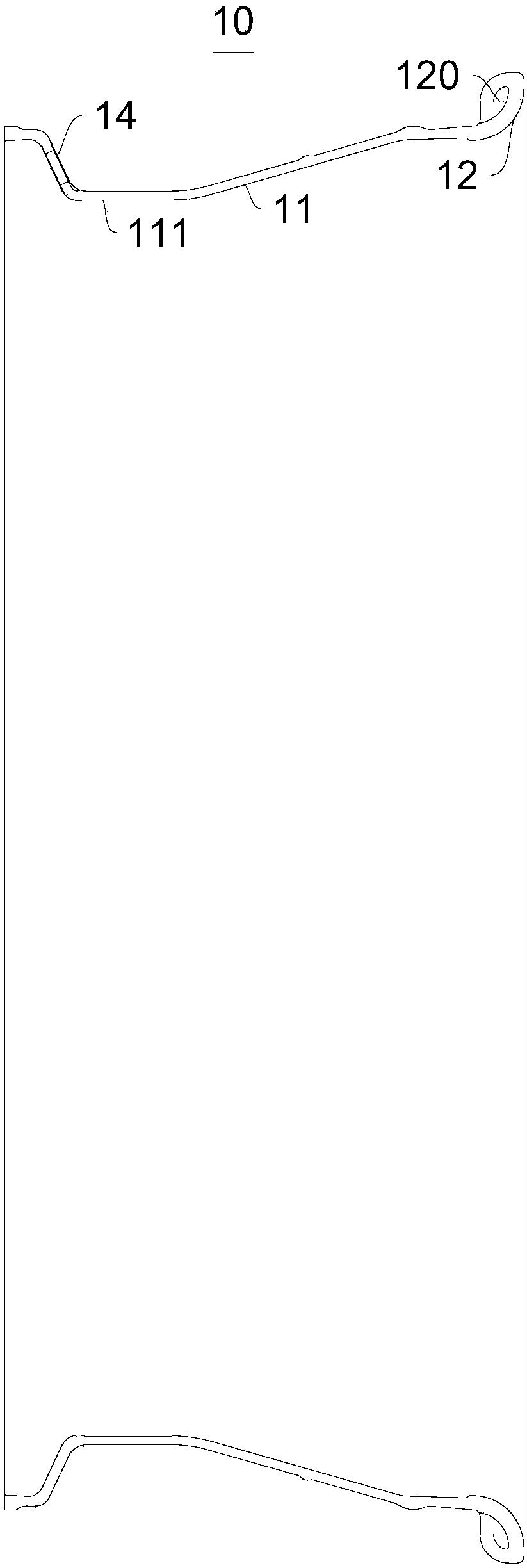
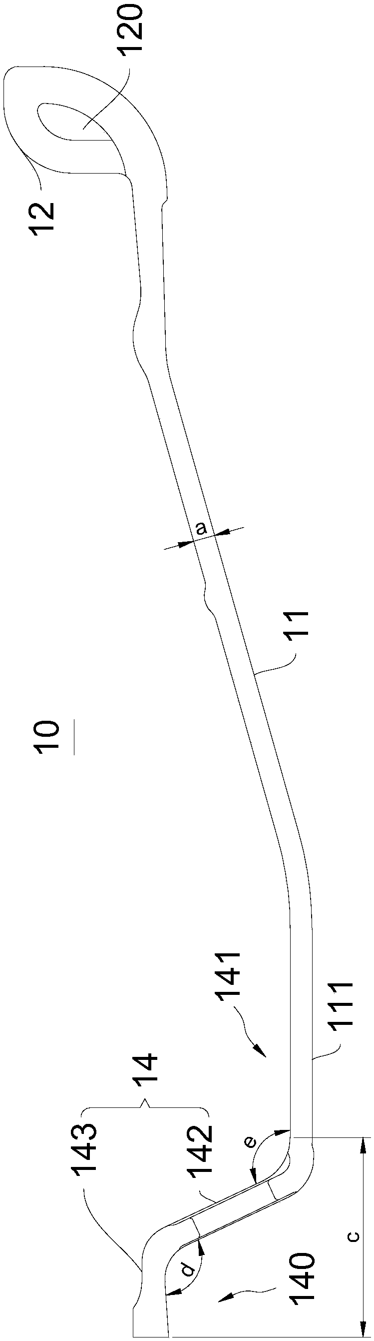
[0081] Please refer to figure 1 and figure 2 , this embodiment provides a rim 10, which includes a rim body 11, the edge of the rim body 11 is provided with a ring-shaped first protrusion, the first protrusion extends in a direction close to the outside of the rim body 11, the first protrusion The rim 12 forming the rim 10 is formed integrally with the rim body 11 .
[0082] The rim 12 and the rim body 11 are integrally formed, and the two are formed at the same time, and the materials of the two can be completely the same, which can ensure the stability of their performance.
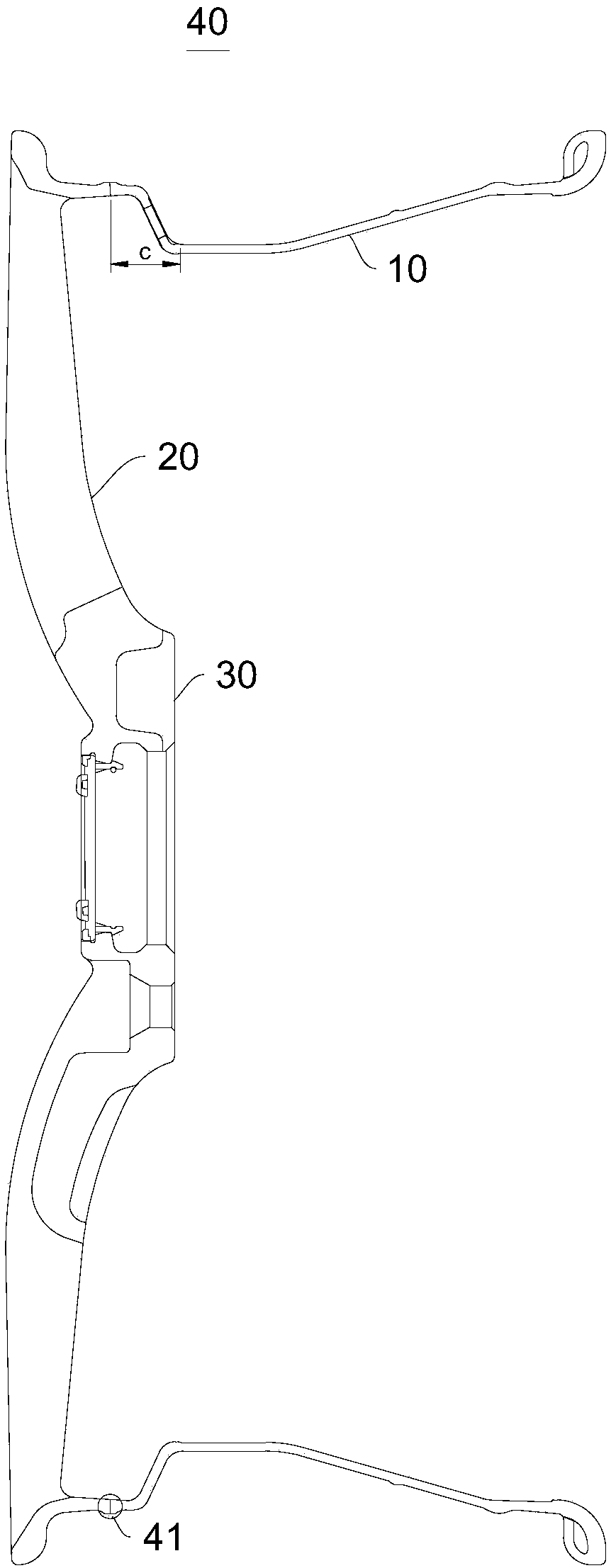
[0083] The rim 12 is convex after molding, which means that its overall size is larger than that of the rim body 11. Generally, it can be understood that its thickness is relatively larger than the thickness of the rim body 11. During use, due to the use of convex Molding mode, after it is combined with wheel spoke 20 etc. to be formed into wheel hub 40 ( image 3 , Figure 4 Shown in), the perform...
Embodiment approach
[0101] It can be understood that, in one embodiment, the end of the rim body 11 can be crimped, and finally the rim 12 can be formed into a convex shape. The ends are pressurized and formed into convex shapes.
[0102] Optionally, the end of the curling structure extends in a direction close to the rim body 11 and closely abuts against the rim body 11 .
[0103] It can be understood that in one embodiment, the degree of curling is relatively complete. In general operation, flanging can be performed first, and then curling, that is to say, two processes are used to ensure the end of the rim body 11. After the part is flanged, a ring is formed locally.
[0104] Optionally, a hollow and airtight second channel is formed in the middle of the curling structure, and the second channel is annular.
[0105] It can be understood that, in one embodiment, after crimping, a relatively airtight second passage is formed in the rim 12 (the second passage is figure 1 , figure 2 in channe...
Embodiment 2
[0123] Please refer to Figure 3-5 , the present embodiment provides a hub 40 , which includes a spoke 20 and the above-mentioned rim 10 , the spoke 20 includes a spoke body 21 , and the end of the spoke body 21 is connected to the end of the rim body 11 away from the rim 12 .
[0124] For the structure of the rim 10, reference may be made to Embodiment 1, and the schematic diagram of the structure involved may be combined with figure 1 and figure 2 .
[0125] The wheel hub 40 in this embodiment adopts modular production, the production of the spokes 20 and the rim 10 are separated, and they are finally welded and formed. The wheel hub 40 has all the excellent characteristics of the rim 10 .
[0126] Optionally, the end of the spoke body 21 is connected to the end of the rim body 11 away from the rim 12 through friction stir welding.
[0127] There are many kinds of welding equipment and operation methods, as long as the two can be fixed. In this embodiment, friction stir...
PUM
| Property | Measurement | Unit |
|---|---|---|
| thickness | aaaaa | aaaaa |
| tensile strength | aaaaa | aaaaa |
| yield strength | aaaaa | aaaaa |
Abstract
Description
Claims
Application Information