Clothes treating device

A clothes processing device and clothes technology, applied in washing devices, other washing machines, textiles and paper making, etc., can solve the problems that users cannot operate the computer controller, and achieve the effect of convenient operation and observation, and convenient use

Pending Publication Date: 2018-04-13
TIANJIN HAIER WASHING ELECTRICAL APPLIANCE CO LTD +1
View PDF6 Cites 6 Cited by
  • Summary
  • Abstract
  • Description
  • Claims
  • Application Information

AI Technical Summary

Problems solved by technology

When the washing machine with this structure is opened, the upper cover will block the computer controller, so that the user cannot perform corresponding operations on the computer controller.

Method used


Image

  • Clothes treating device
  • Clothes treating device
  • Clothes treating device

Examples


Embodiment 1

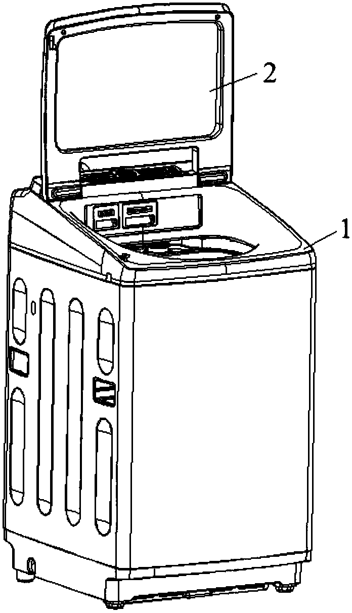
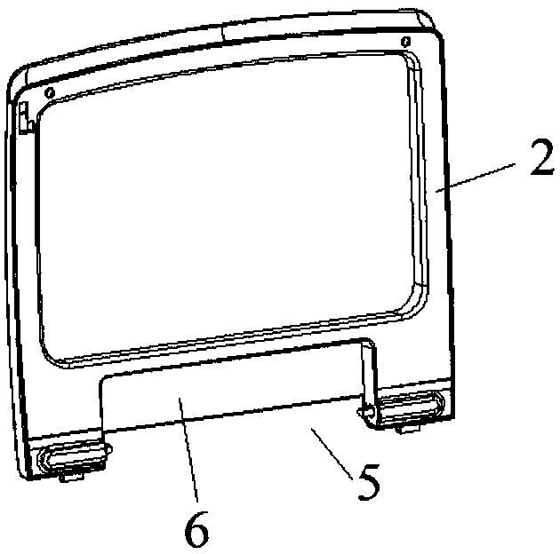
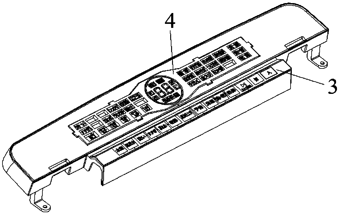
[0041] Such as figure 2 , image 3 As shown, the notch structure described in this embodiment is square, located at the lower edge of the upper cover 2 when the cover is opened, that is, the side of the lower edge of the upper cover 2 is a U-shaped structure, and the transparent device is the shape and display of the observation area 6. Similar to the screen 4, the transparent device is a glass window, which is fixed on the shell of the upper cover 2, and a part is covered at the gap structure, and does not protrude from the upper surface of the upper cover 2, that is, the glass window and the upper surface of the upper cover 2 There are no steps or ribs at the contact point of the cover 2. When the cover 2 is closed, the edge of the glass window in the direction of the rotation axis of the cover 2 is parallel to and in close contact with the front side wall of the control area 3; the area of ​​the transparent device is larger than that of the display screen 4, to ensure tha...

Embodiment 2

[0043] Such as figure 2 , image 3 As shown, the operating area 5 described in this embodiment is a notch on the upper cover 2 that is not covered by the transparent device. The operating area 5 is square, and the two boundaries of the operating area 5 perpendicular to the rotation axis of the upper cover 2 are the upper The gap boundary of the cover 2 is parallel to and in close contact with the left and right side walls of the control area 3, and is fixedly connected by a damping hinge; when the upper cover 2 is opened, the two boundaries of the operating area 5 parallel to the rotation axis of the upper cover 2 are respectively The edge of the observation area 6 is in close contact with the upper surface of the control area 3, and the upper cover 2 is closed, and the edge of the observation area 6 is in close contact with the front side wall of the control area 3, that is, the area of ​​the operation area 5 is zero, that is, the gap is closed, Prevent liquid from overflow...

Embodiment 3

[0045] Such as figure 2 , image 3 As shown, the width of the control area 3 in this embodiment in the direction perpendicular to the rotation axis of the upper cover 2 is greater than the height of the control area 3 , and when the upper cover 2 is opened, the edge of the operation area 5 is higher than the control area 3 , if the rotation axis of the upper cover 2 is at the rear side wall of the control area 3, the width of the control area 3 in the direction perpendicular to the rotation axis of the upper cover 2 is greater than the height of the control area 3; if the rotation axis of the upper cover 2 is at the control area 3 In the middle of the front and rear side walls, the half of the width of the control area 3 in the direction perpendicular to the rotation axis of the upper cover 2 is greater than the height of the control area 3 .


PUM


Abstract

The invention discloses a clothes treating device. The clothes treating device comprises a control panel base, a clothes input opening and an upper cover, wherein the clothes input opening is formed in the control panel base and used for taking and inputting clothes, and the upper cover is located above the clothes input opening and connected with the control panel base and is capable of being overturned backwards so as to uncover the clothes input opening. A display screen is arranged on the portion, behind the clothes input opening, of the control panel base, an observation area is arrangedon the upper cover and used for observing the rear display screen from the front of the upper cover in the uncovering state, control areas for controlling the clothes treating device are arranged on the front side and/or the lateral side of the display screen, the control areas and the display screen form a control panel, and an operation area capable of operating the control areas from the frontof the upper cover in the uncovering state is arranged on the upper cover. According to the clothes treating device with the rear control panel, under the conditions that the upper cover is closed andopened, the operation on the clothes washing procedure can be achieved, and under the condition that the upper cover is opened, the display conditions of the control panel can be observed through a transparent window.

Description

technical field [0001] The invention belongs to the field of household appliances, and in particular relates to a clothes processing device. Background technique [0002] In the current computer-controlled fully automatic washing machine, the computer boards of the control part are all designed to be installed on the front of the panel, and the user often puts wet clothes on the operation surface of the control part when using it. A layer of film is used to block it, but the washing liquid and water on the clothes can still pass through the film and seep into the computer board, which will affect the safety of use. [0003] The Chinese patent application number CN96227283.3 discloses a rear-mounted fully automatic washing machine with a computer program controller, which is an improvement of the installation position and installation structure of the computer control part of the fully automatic washing machine on the panel. The computer control part is installed on the rear...

Claims


Application Information

Patent Timeline
Patent Type & Authority Applications(China)
IPC IPC(8): D06F39/00D06F39/14D06F34/32
CPCD06F34/32D06F2105/58D06F2101/00
Inventor 吕佩师程宝珍张令全孙广彬
Owner TIANJIN HAIER WASHING ELECTRICAL APPLIANCE CO LTD
Why Eureka
Try Eureka