Integrated supporting system for connection of fabricated shear walls and laminated slab and mounting method
A technology of support system and shear wall, which is applied in the field preparation and construction of pillars and building components, can solve the problems of cumbersome installation and removal of under-slab supports, insufficient wall lap length, etc., to meet construction safety requirements and solve problems Difficult construction and reduced formwork difficulty
- Summary
- Abstract
- Description
- Claims
- Application Information
AI Technical Summary
Problems solved by technology
Method used
Image
Examples
Embodiment 1
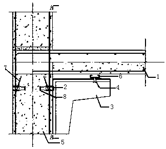
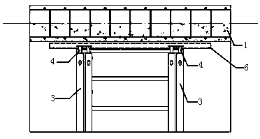
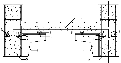
[0044] Such as Figure 1-Figure 6 As shown, the present invention is an assembled shear wall laminated plate connection integrated support system, including a support frame 3 symmetrically arranged on one side of the shear wall 5, an adjusting bolt 4 arranged between the support frame 3 and the laminated plate 1 and Support plate 6, two support frames 3 are arranged side by side along each side of the shear wall 5, the cross section of the support frame 3 is an irregular frame, and its right-angled sides correspond to the shear wall 5 and the laminated plate 1 respectively, and the relative shear wall 5 Bolt connection reserved holes are provided on the right-angled side of the side, which is connected to the embedded nut 2 provided on the side of the shear wall 5 through bolts; the adjusting bolt 4 is connected to the right-angled side of the laminated plate 1. 5 The adjustment bolt 4 on the support frame 3 on the same side is connected to the support plate 6, and the laminat...
Embodiment 2
[0060] The difference between this example and Example 1 is that the outer periphery of the embedded nut 2 provided on the shear wall 5 in this example is provided with a U-shaped rib 7 with an inclination angle of 30° relative to the horizontal plane. What the support plate 6 of this example adopted was a channel frame made by welding steel plates. Such as Figure 10 , Figure 11 As shown, there is a stopper 8 at the end of the embedded nut 2 described in this example that is not connected to the bolt, and the stopper 8 is arranged in a cross-shaped structure along the circumference of the end, which is convenient for installation and fixation.
Embodiment 3
[0062] The difference between this example and Example 1 is that the outer periphery of the embedded nut 2 provided on the composite beam 5 in this example is provided with a U-shaped rib 7 with an inclination angle of 40° relative to the horizontal plane.
PUM
 Abstract
Description
Claims
Application Information
 - R&D
- Intellectual Property
- Life Sciences
- Materials
- Tech Scout
- Unparalleled Data Quality
- Higher Quality Content
- 60% Fewer Hallucinations
Browse by: Latest US Patents, China's latest patents, Technical Efficacy Thesaurus, Application Domain, Technology Topic, Popular Technical Reports.
© 2025 PatSnap. All rights reserved.Legal|Privacy policy|Modern Slavery Act Transparency Statement|Sitemap|About US| Contact US: help@patsnap.com


