Prefabricated composite beam-plate connection support device with height difference on top of plate and installation method thereof
A technology of supporting devices and superimposed beams, which is applied to floors, building components, buildings, etc., can solve the problems of cumbersome installation and dismantling of under-slab supports, insufficient wall lap length, etc., to meet construction safety requirements, solve construction difficulties, and on-site Simple to use effects
- Summary
- Abstract
- Description
- Claims
- Application Information
AI Technical Summary
Problems solved by technology
Method used
Image
Examples
Embodiment 1
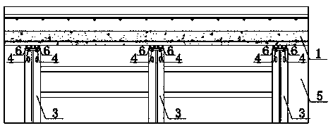
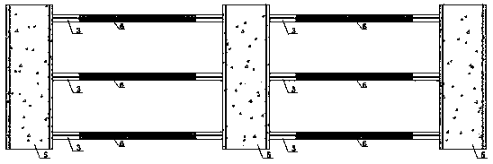
[0046] Such as Figure 1~Figure 6 As shown, the present invention is a support structure for the composite beam-slab connection of the assembled structure, including the support frame 3 arranged on both sides of the composite beam 5, the adjusting bolt 4 provided between the support frame 3 and the composite plate 1 and Support plate 6, the support frame 3 is arranged three side by side along each side of the laminated beam 5, the section of the support frame 3 is an irregular frame, and its right-angled sides correspond to the laminated beam 5 and the laminated plate 1 respectively, and the relative composite beam 5 Bolt connection reserved holes are provided on the right-angle side of the side, and are connected to the embedded nut 2 provided on the side of the composite beam 5 by bolts; They are connected by adjusting bolts 6, and the height of the supporting plate 6 is adjusted by adjusting the adjusting bolts 4 between the supporting plate 6 and the supporting frame 3 dur...
Embodiment 2
[0062] The difference between this example and Example 1 is that in this example, the embedded nut 2 provided on the composite beam 5 in this example is provided with a U-shaped rib 7 on the outer periphery, and the angle α inclined relative to the horizontal plane is 30°. What the support plate 6 of this example adopted was a channel frame made by welding steel plates. Such as Figure 10 , Figure 11 As shown, there is a stopper 8 at the end of the embedded nut 2 described in this example that is not connected to the bolt, and the stopper 8 is arranged in a cross-shaped structure along the circumference of the end, which is convenient for installation and fixation.
Embodiment 3
[0064] The difference between this example and Example 1 is that the outer periphery of the embedded nut 2 provided on the composite beam 5 in this example is provided with U-shaped ribs 7 , and the angle α inclined relative to the horizontal plane is 40°.
PUM
 Abstract
Description
Claims
Application Information
 - R&D
- Intellectual Property
- Life Sciences
- Materials
- Tech Scout
- Unparalleled Data Quality
- Higher Quality Content
- 60% Fewer Hallucinations
Browse by: Latest US Patents, China's latest patents, Technical Efficacy Thesaurus, Application Domain, Technology Topic, Popular Technical Reports.
© 2025 PatSnap. All rights reserved.Legal|Privacy policy|Modern Slavery Act Transparency Statement|Sitemap|About US| Contact US: help@patsnap.com


