Supporting structure for fabricated structure beam plate connection and mounting method

A technology of supporting structures and structural beams, which is applied in the direction of building construction and construction, can solve the problems of cumbersome installation and removal of under-slab supports, insufficient beam lap length, etc., to meet construction safety requirements, reduce the difficulty of formwork support, and facilitate on-site operation simple effect

Inactive Publication Date: 2017-08-18
SHENYANG JIANZHU UNIVERSITY
View PDF0 Cites 15 Cited by
  • Summary
  • Abstract
  • Description
  • Claims
  • Application Information

AI Technical Summary

Problems solved by technology

[0007] Aiming at the above-mentioned technical problems such as insufficient beam lap length at the beam-slab connection node of the prefabricated building, post-cast formwork support at the node, and cumbersome installation and removal of the support under the slab, the present invention provides a support for the beam-slab connection of the prefabricated structure Structure and installation method

Method used


Image

  • Supporting structure for fabricated structure beam plate connection and mounting method
  • Supporting structure for fabricated structure beam plate connection and mounting method
  • Supporting structure for fabricated structure beam plate connection and mounting method

Examples


Embodiment

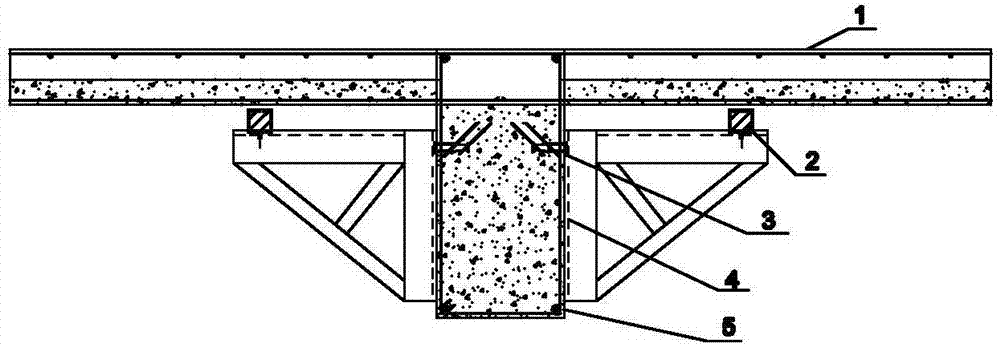
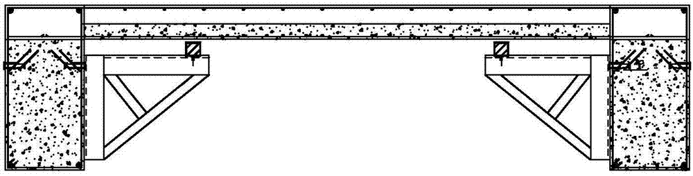
[0043] Example: such as Figure 1-Figure 6 As shown, the present invention is a supporting structure for the connection of assembled structural beams and slabs, including the support frame 4 symmetrically arranged on both sides of the composite beam 5, the adjustment frame 2 and the support plate arranged between the support frame 4 and the composite plate 1 6. Two support frames 4 are arranged side by side along each side of the laminated beam 5. The cross section of the support frame 4 is a triangular frame structure, and its right-angled sides correspond to the laminated beam 5 and the laminated plate 1 respectively, and the opposite side of the laminated beam 5 Bolt connection holes are provided on the right-angled side of the composite beam 5, which are connected to the embedded nut 3 provided on the side of the composite beam 5; The adjustment frame 2 on the support frame 6 is connected with a support plate 6, and the laminated plate 1 is placed above the support plate 6...

Embodiment 2

[0058] Embodiment 2: The difference between this embodiment and Embodiment 1 is that the outer periphery of the embedded nut 3 provided on the composite beam 5 in this embodiment is provided with U-shaped ribs, and the angle α inclined relative to the horizontal plane is 30°. What this example support plate 6 adopted is the wooden side. like Figure 9 , Figure 10 As shown, there is a stopper 8 at the end of the embedded nut 3 not connected to the bolt in this example, and the stopper 8 is arranged in a cross-shaped structure along the circumference of the end, which is convenient for installation and fixation.

Embodiment 3

[0059] Embodiment 3: The difference between this embodiment and Embodiment 1 is that the embedded nut 3 provided on the composite beam 5 in this embodiment is provided with a U-shaped rib on the outer periphery, and the angle α inclined relative to the horizontal plane is 40°.


PUM


Abstract

The invention relates to a support structure and an installation method for connecting beams and slabs of an assembled structure, which belong to the technical field of building structures. It is a frame structure composed of two symmetrical support frames connected by support plates. The cross section of the support frame is a triangular frame structure, and its right-angled sides correspond to the laminated beam and laminated plate respectively, and bolt connection holes are provided on the right-angled side of the opposite composite beam side. , connected to the pre-embedded nuts provided on the side of the composite beam through bolts; the adjustment frame is connected to the right-angled side of the composite plate. When in use, the adjustment frame on the support frame in the adjacent two composite beams is connected with a support plate , the laminated plate is placed above the supporting plate and connected to the two laminated beams, and the height of the supporting plate is adjusted through the adjusting bolts connected between the adjusting frame and the supporting frame. The invention cancels the vertical support of the lower part of the floor slab, thereby reducing the difficulty of setting up the formwork and saving costs, and can meet the construction accuracy. The invention is easy to operate on site, and can effectively solve the problems of difficult construction when beams and slabs are overlapped, reinforcement, support and removal of formwork for post-cast joints.

Description

technical field [0001] The invention belongs to the technical field of building structures, and in particular relates to a supporting structure and an installation method for connecting beams and slabs of an assembled structure. Background technique [0002] With the increasing development of prefabricated buildings, the connection of various components of prefabricated buildings will also become frequent and important. In the connection of prefabricated building structural components, the beam-slab connection is a very common existence. In this connection form, one end of the laminated slab is lapped on the edge of the laminated beam, the upper part of the slab is hoisted by a crane, and the bottom is supported vertically. [0003] However, there are three main problems in the beam-slab connection: [0004] First, the length of the floor support. As far as composite beams are concerned, the protective layer is generally 15-20mm. In the actual structural lap joint, due t...

Claims


Application Information

Patent Timeline
Patent Type & Authority Applications(China)
IPC IPC(8): E04B1/04E04B1/21
CPCE04B1/043E04B1/21
Inventor 孟宪宏毕佳男夏程
Owner SHENYANG JIANZHU UNIVERSITY
Why Eureka
Try Eureka