Annular pipe jacking machine

A pipe jacking machine and annular technology, which is used in wellbore lining, tunnel lining, underground chamber, etc., can solve the problem of difficult size, and achieve the effect of stable excavation surface, environmental protection, and flexible cross-section shape.

Inactive Publication Date: 2015-06-17
TONGJI UNIV
View PDF7 Cites 17 Cited by
  • Summary
  • Abstract
  • Description
  • Claims
  • Application Information

AI Technical Summary

Problems solved by technology

[0004] Full-section pipe jacking is limited by the existing technology, and it is difficult to make a breakthrough in size. Therefore, a new type of pipe jacking construction machine suitable for the construction of large-diameter underground passages in heavy traffic areas is sought

Method used


Image

  • Annular pipe jacking machine
  • Annular pipe jacking machine
  • Annular pipe jacking machine

Examples


Embodiment 1

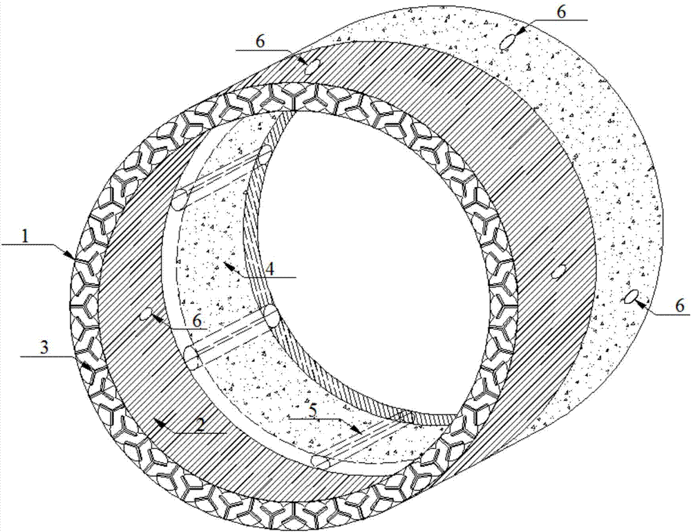
[0035] This embodiment provides an annular pipe jacking machine, which includes an annular shell, a cutting cutter head, a slurry system, a synchronous grouting system, a pushing mechanism, a guiding system and a control system, and a pipe jacking joint 4 is connected to the rear of the machine.

[0036] Such as figure 1 As shown, the annular shell includes an outer shell 1 and an inner shell 2 , which together form an annular cavity for accommodating a cutting disc 3 . The outer shell 1 supports the surrounding stratum soil, and at the same time, the jacking of the pipe jacking joint 4 is completed under the protection of the outer shell 1 . At the place where the structural bending moment of the pipe jacking joint 4 is small, several hollow passages 5 are provided as passages for placing mud inlet and discharge pipes, grouting pipes, cables and hydraulic oil pipes, etc. Several grouting holes 6 are arranged on the side where the outer shell 1 , the inner shell 2 and the pip...

Embodiment 2

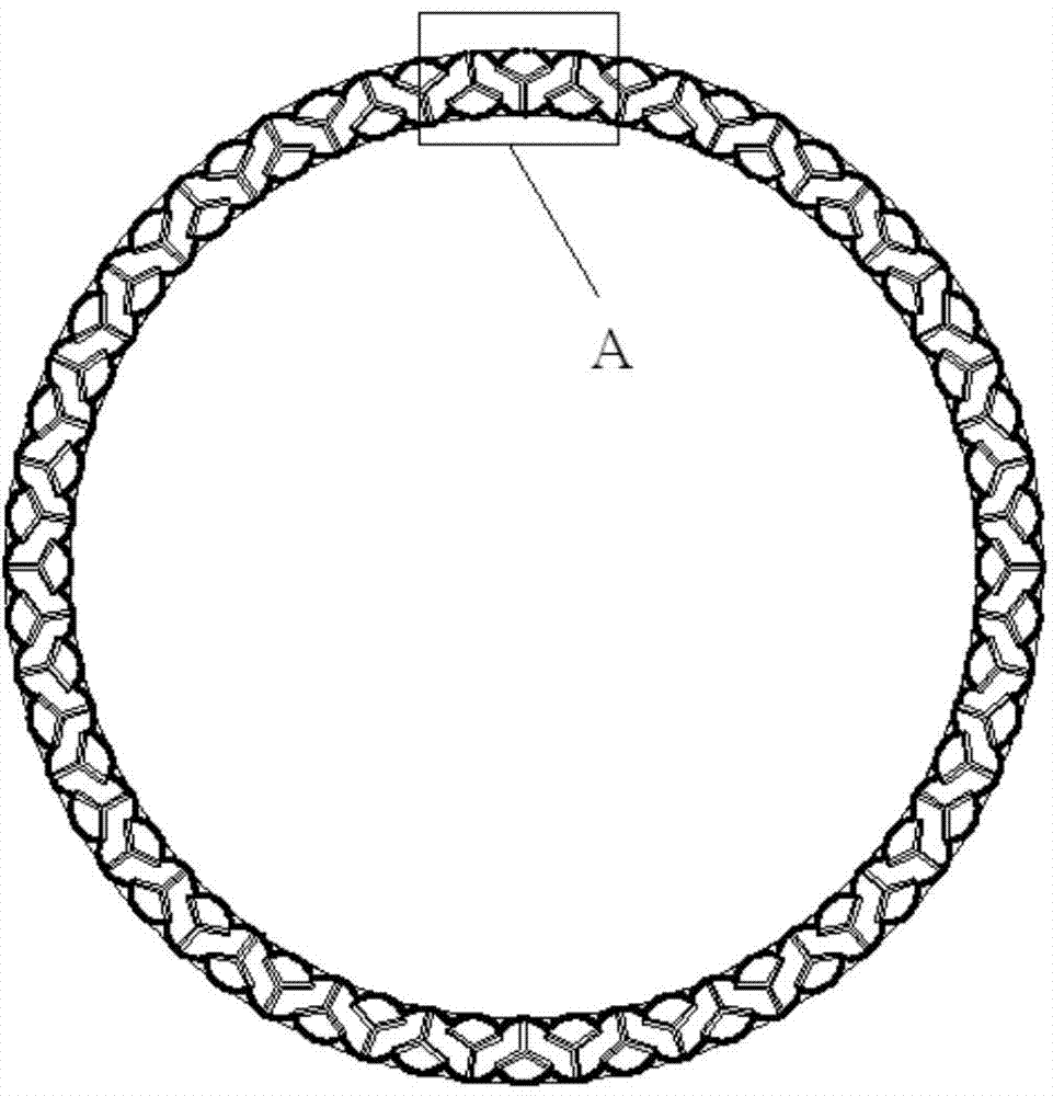
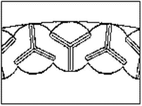
[0046] Such as Figure 4-5 As shown, the cutting disc 3 is composed of a plurality of staggered small discs, which detachably cover the entire annular area, and the rest are the same as in the first embodiment.

[0047] Such as Figure 7 As shown, the specific working steps of the above ring pipe jacking machine include the following points:

[0048] (1) Use the construction technology of the existing pipe jacking method to construct the working well 27, the receiving well 28 and the retaining wall 29, and reinforce the soil on the working face of the annular pipe jacking machine;

[0049] (2) Hoist ring pipe jacking machine, top iron 30, jack 25, lay mud inlet pipeline 14, mud discharge pipeline 15, grouting pipe 16, hydraulic oil pipe 31, cable 26, install mud-water separation treatment equipment, mud pump, etc. Grouped equipment;

[0050] (3) The circular pipe jacking machine is started, the starting operation is completed, and the pipe jacking section 4 is hoisted;

[...


PUM


Abstract

The invention relates to an annular pipe jacking machine which comprises an annular shell, a cutter head, a muddy water system, a synchronous grouting system, a jacking mechanism, a guide system and a control system. The annular shell comprises an outer-layer shell body and an inner-layer shell body, the cutter head is arranged in the annular shell, the muddy water system comprises a mud inlet and outlet pipeline and a mud and water separation treatment device, the mud and water separation treatment device is arranged on the ground, grouting pipes of the synchronous grouting system are arranged in the annular shell and sections of a jacking pipe respectively, thixotropic slurry is injected through a grouting hole, the jacking mechanism is arranged in a jacking pipe work well and used for jacking the sections of the jacking pipe, the guide system comprises a gyroscope, a tilt meter and a height gauge which are used for determining the posture of the annular pipe jacking machine and tunneling precision, and the control system is arranged on the ground and used for performing cooperative control on the cutter head, the muddy water system, the synchronous grouting system, the jacking mechanism and the guide system. Compared with the prior art, an excavated section is small, the shape of the section is flexible, and the annular pipe jacking machine is suitable for building tunnels with large sections and extra-large sections.

Description

technical field [0001] The invention relates to a pipe jacking construction machine, in particular to an annular pipe jacking machine. Background technique [0002] In major cities in China, the development of urban municipal engineering has entered a new stage. Especially in underground projects that are adjacent to or pass through existing buildings (structures), the restriction on the impact on the environment leads to higher requirements for tunnel construction methods and technologies. Taking Shanghai as an example, in the construction of underground passages, it is often impossible to use the open cut method for construction, while the shield tunneling method is expensive when the tunnel length is short, and the urban environment constraints also make it difficult to transport and install large shield tunneling equipment. [0003] As a trenchless technology, the pipe jacking method has the advantages of not affecting traffic and having little impact on the environment...

Claims


Application Information

Patent Timeline
Patent Type & Authority Applications(China)
IPC IPC(8): E21D9/00E21D9/10E21D11/10
CPCE21D9/001E21D9/1006E21D9/1086E21D11/10
Inventor 白云李乔松陈昂
Owner TONGJI UNIV
Why Eureka
Try Eureka