Dynamic frequency real-time adjustable micro-displacement motion platform

A technology of dynamic frequency and motion platform, which is applied in the direction of machine/support, generator/motor, piezoelectric effect/electrostrictive or magnetostrictive motor, etc., which can solve the problem of large damage to driving components and large influence of external factors , susceptible to damage and other issues, to avoid lateral loads, reduce coupling motion, and achieve good decoupling performance

Active Publication Date: 2018-04-13
SHANDONG UNIV
View PDF10 Cites 5 Cited by
  • Summary
  • Abstract
  • Description
  • Claims
  • Application Information

AI Technical Summary

Problems solved by technology

[0003] Chinese invention patent CN102825490A discloses a frequency-adjustable fast-knife servo feed device based on a flexible hinge amplifying mechanism. The device uses piezoelectric ceramics to directly drive a lever mechanism to realize platform movement, so that piezoelectric ceramics are subjected to shear force during feeding. , easy to be damaged, in addition, the prestressed film cannot be adjusted automatically, and real-time continuous adjustment cannot be realized
[0004] Chinese invention patent CN102528522A discloses a fast knife servo with adjustable stiffness. This mechanism adjusts the applied pressure of the spring by manually rotating the spring sleeve. In the process of stiffness adjustment, it is greatly affected by human factors, and it is also impossible to achieve real-time and accuracy. adjustment
[0005] To sum up, most of the existing adjustable stiffness platforms realize frequency adjustment by compressing springs or screws to apply pre-tightening force. In the process of manual adjustment, they are greatly affected by external factors, and at the same time, the input end often The asymmetric layout will cause great damage to the driving components. In addition, the existing dynamic platform structure cannot realize real-time adjustment of frequency, and cannot meet the high requirements of a modern dynamic platform.

Method used


Image

  • Dynamic frequency real-time adjustable micro-displacement motion platform
  • Dynamic frequency real-time adjustable micro-displacement motion platform
  • Dynamic frequency real-time adjustable micro-displacement motion platform

Examples


Embodiment Construction

[0030] It should be pointed out that the following detailed description is exemplary and intended to provide further explanation to the present application. Unless defined otherwise, all technical and scientific terms used herein have the same meaning as commonly understood by one of ordinary skill in the art to which this application belongs.

[0031] It should be noted that the terminology used here is only for describing specific implementations, and is not intended to limit the exemplary implementations according to the present application. As used herein, unless the context clearly dictates otherwise, the singular is intended to include the plural, and it should also be understood that when the terms "comprising" and / or "comprising" are used in this specification, they mean There are features, steps, operations, means, components and / or combinations thereof.

[0032] As introduced in the background technology, there are deficiencies in the prior art that the dynamic plat...


PUM


Abstract

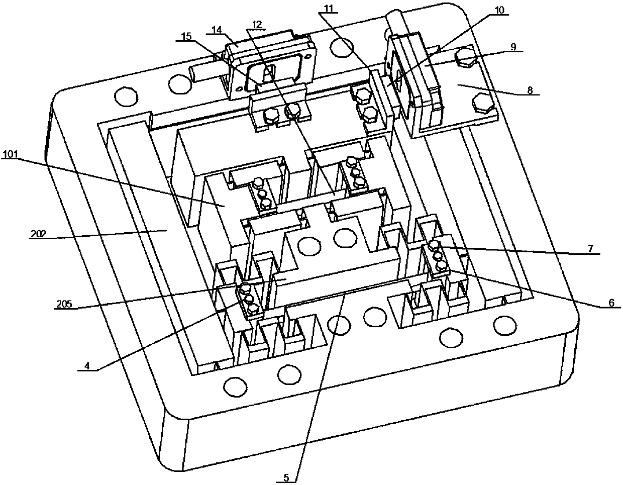
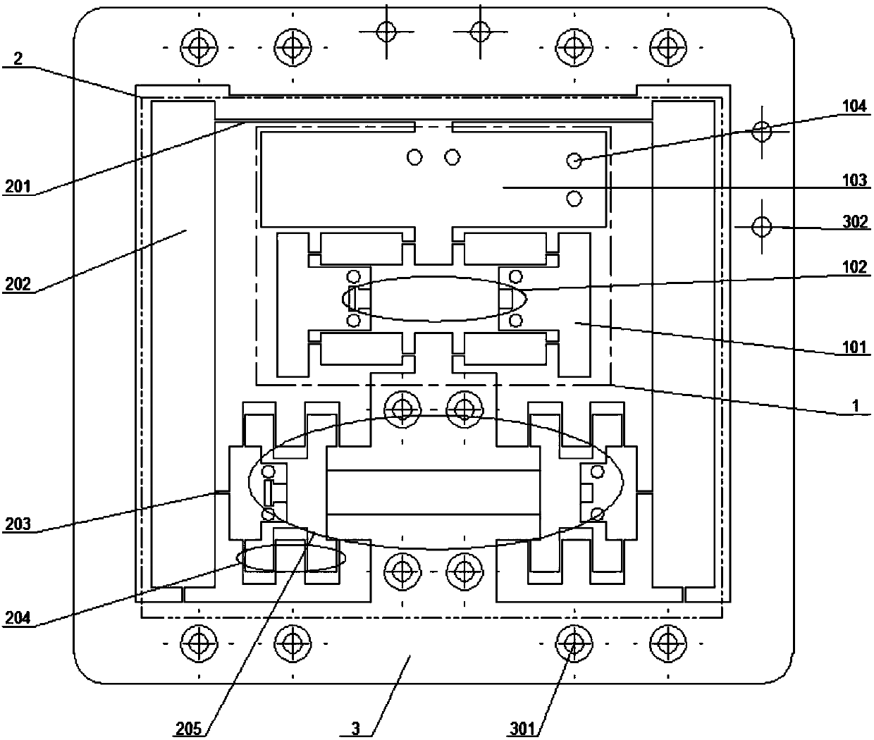
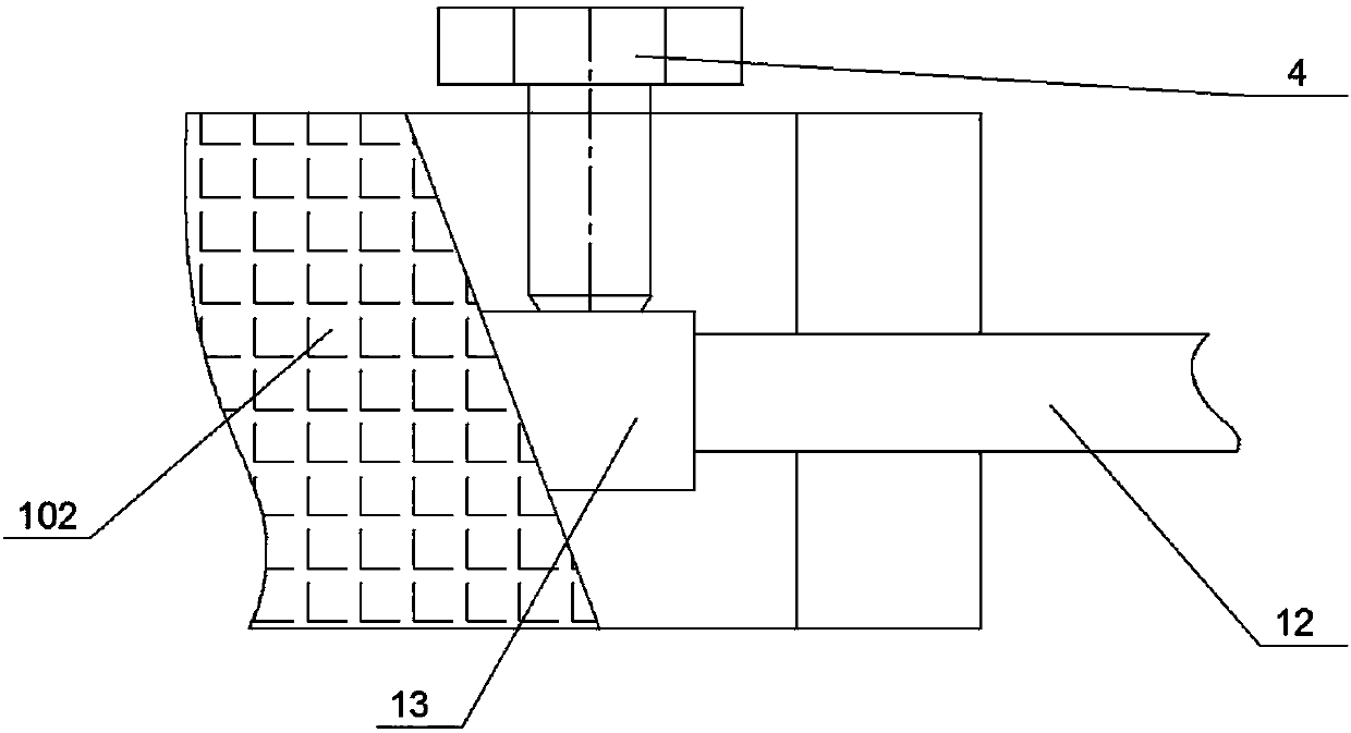
The invention discloses a dynamic frequency real-time adjustable micro-displacement motion platform. The micro-displacement motion platform solves the problems that an dynamic platform structure in the prior art cannot achieve real-time adjusting frequency and the high requirement of a modern dynamic platform cannot be met are solved. The micro-displacement motion platform has the advantages thatthe output displacement and the output frequency of the motion platform can be adjusted in real time, the layout is compact and motion precision is high are achieved. According to the technical scheme, the micro-displacement motion platform comprises a motion driving assembly and a rigidity adjusting assembly which are connected with a motion table; the motion driving assembly is provided with a bridge type amplifying mechanism, and the input displacement of the moving table is amplified through the bridge type amplifying mechanism; and the rigidity adjusting assembly is provided with a leveramplifying mechanism, a plate spring sheet is arranged at the tail end of the lever amplifying mechanism, and the plate spring sheet is deformed by the displacement generated by the tail end of the lever amplifying mechanism so as to change the output frequency of the moving table.

Description

technical field [0001] The invention relates to a precision motion platform, in particular to a micro-displacement motion platform with real-time adjustable dynamic frequency. Background technique [0002] The micro-displacement motion mechanism is the key core mechanism in the modern micro-nano positioning high-tech and precision equipment industry. It has great prospects in the fields of ultra-precision manufacturing, biomedical testing instruments, and fine processing of complex curved surfaces. Most of the micro-displacement mechanisms widely used at present are fixed-frequency mechanisms, which can only work at one frequency point. In addition, due to the inaccuracy in the simulation analysis and the inevitable errors in the manufacturing process, the mechanism cannot achieve the desired dynamic characteristics. These shortcomings are increasingly unable to meet the high requirements in the modern precision equipment industry. Therefore, the development and design of...

Claims


Application Information

Patent Timeline
IPC IPC(8): F16M11/04F16M11/18H02N2/04
CPCF16M11/043F16M11/18H02N2/043
Inventor 闫鹏李建明
Owner SHANDONG UNIV
Why Eureka
Try Eureka