LED lamp mounting structure

A technology of LED lamp and installation structure, applied in the direction of lampshade, lighting device, fixed lighting device, etc., can solve the problems of LED lamp without lamp board, inconvenient installation, installation of lamp board, etc. The effect of installation efficiency

Active Publication Date: 2018-04-13
郭峰
View PDF6 Cites 8 Cited by
  • Summary
  • Abstract
  • Description
  • Claims
  • Application Information

AI Technical Summary

Problems solved by technology

[0004] However, the existing LED lamps do not have light boards and buckles, and the light boards cannot be installed through the buckles. They need to be installed with screws, which is not easy to install.

Method used


Image

  • LED lamp mounting structure
  • LED lamp mounting structure
  • LED lamp mounting structure

Examples


Embodiment Construction

[0017] The following will clearly and completely describe the technical solutions in the embodiments of the present invention with reference to the accompanying drawings in the embodiments of the present invention. Obviously, the described embodiments are only some, not all, embodiments of the present invention.

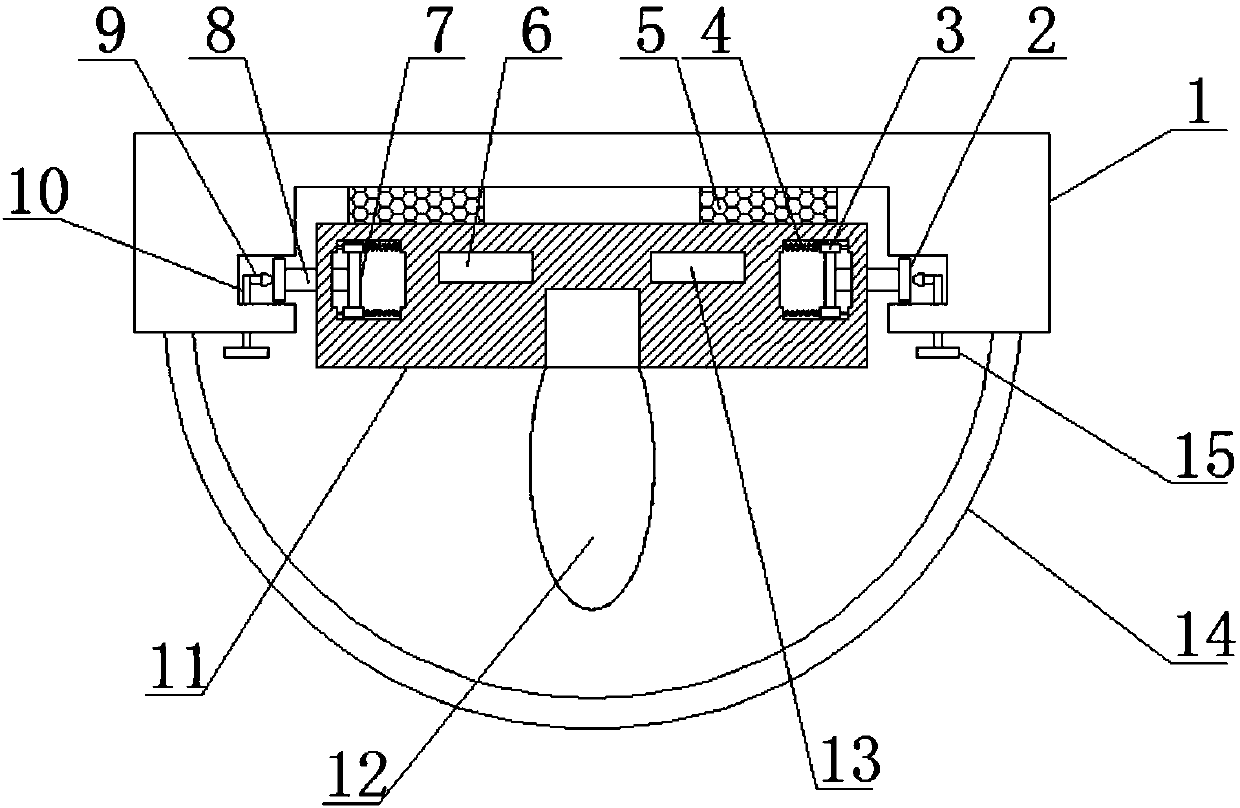
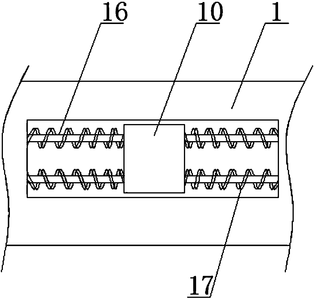
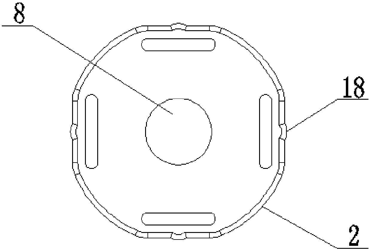
[0018] refer to Figure 1-3 , an LED lamp installation structure, including a base plate 1, a groove is provided at the lower end of the base plate 1, a rubber pad 5 is fixedly connected to the inner wall of the groove, the rubber pad 5 can play a buffering role, and a lamp board 11 is arranged in the groove , when in use, the operator fixes the bottom plate 1 on the ceiling, and then places the lamp board 11 in the groove. There are two device cavities inside the lamp board 11, and guide grooves are provided on the opposite inner walls of the device cavities. Inside the guide grooves Be provided with guide rod 4, the two ends of guide rod 4 are fixedly connected on ...


PUM


Abstract

The invention discloses an LED lamp mounting structure comprising a bottom plate. A groove is formed in the lower end of the bottom plate, and rubber blankets are fixedly connected with the inner wallof the groove; a lamp plate is disposed in the groove, and two device cavities are arranged in the lamp plate; guiding grooves are formed in the opposite inner walls of the device cavities, and guiding rods are disposed in the guiding grooves, and both ends of the guiding rods are fixedly connected to the inner walls of the guiding grooves; the guiding rods are sleeved with movable blocks, and the movable blocks are movably connected with the guiding rods; the portions, located between the movable blocks and the inner walls of the guiding grooves, of the guiding rods are provided with springs; and movable rods are arranged in the device cavities, two ends of each of the movable rods are correspondingly and fixedly connected to the sidewalls of two movable blocks, and push rods are arranged on the side walls of the movable rods. According to the LED lamp mounting structure, the structure design is reasonable, the operation is simple, the lamp plate is easy to be disassembled and installed, and the installation efficiency of the LED lamp is greatly improved.

Description

technical field [0001] The invention relates to the technical field of LED lamps, in particular to an LED lamp installation structure. Background technique [0002] LED (Light Emitting Diode), light-emitting diode, is a solid-state semiconductor device that can convert electrical energy into visible light, and it can directly convert electricity into light. The heart of LED is the wafer of a semiconductor, and one end of wafer is attached on a bracket, and one end is negative pole, and the other end connects the positive pole of power supply, and whole wafer is encapsulated by epoxy resin. [0003] Semiconductor wafer is made up of two parts, and a part is P-type semiconductor, and hole occupies an leading position in it, and the other end is N-type semiconductor, and here mainly is electron. But time these two kinds of semiconductors couple together, between them, just form a P-N junction. When electric current acts on this chip by wire time, electron will be pushed to P ...

Claims


Application Information

Patent Timeline
Patent Type & Authority Applications(China)
IPC IPC(8): F21S8/04F21V21/03F21V19/00F21V15/04F21V3/06F21Y115/10
CPCF21S8/04F21V15/04F21V19/004F21V21/03F21Y2115/10
Inventor 郭峰
Owner 郭峰
Why Eureka
Try Eureka