Medium loading adjustable filter, design method thereof, and adjustable duplexer

A dielectric loading and filter technology, which is applied to waveguide devices, electrical components, circuits, etc., can solve the problems of in-band echo deterioration, reduced motor life, and motors that cannot push the tuning plate, and achieve almost constant bandwidth Effect

Active Publication Date: 2018-04-13
PIVOTONE COMM TECH
View PDF10 Cites 4 Cited by
  • Summary
  • Abstract
  • Description
  • Claims
  • Application Information

AI Technical Summary

Problems solved by technology

But these two methods have disadvantages: 1. The filters themselves of these two forms of adjustable filters are all filters in the form of E-face metal diaphragm partitions. This is due to the thickness of the diaphragm at the input and output ends. Very thin, therefore, the bandwidth of this form of filter cannot be made very wide, and the metal diaphragm is easily damaged, which fundamentally limits the performance of these two adjustable filters; 2. The filter divides the resonant cavity between The partition wall adopts a diaphragm structure, resulting in the tuning mechanism can only be adjusted in half of the cavity, which limits the tuning range and results in a wide enough tuning bandwidth. According to reports, the adjustable bandwidth is only 2%-5%;3 , Out-of-band suppression, in-band insertion loss and in-band echo deteriorate seriously during the tuning process, and the bandwidth changes continuously with tuning
[0005] In addition, the biggest disadvantage of the NEC solution is that the dielectric sheet can only rotate 90 degrees at most, so the tuning is very sensitive. In order to reduce the sensitivity of tuning, NEC uses a reduction structure composed of multiple gears similar to a gearbox. This structure reduces tuning. However, the disadvantages of th

Method used


Image

  • Medium loading adjustable filter, design method thereof, and adjustable duplexer
  • Medium loading adjustable filter, design method thereof, and adjustable duplexer
  • Medium loading adjustable filter, design method thereof, and adjustable duplexer

Examples


Embodiment Construction

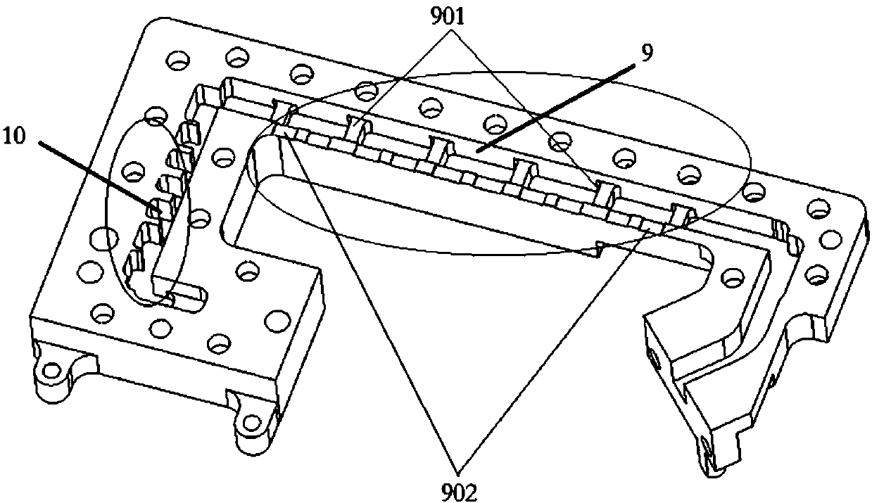
[0037] Aiming at the deficiencies of the existing technology, the idea of ​​the present invention is to open a slot in the center of the E-plane and use a comb-shaped tuning dielectric sheet as the tuning mechanism on the basis of the E-plane waveguide filter, so as to obtain a filter with better electrical performance. , and the structure is simpler and the production cost is lower than that of the medium-loaded tunable filter.

[0038] Specifically, the media-loaded tunable filter of the present invention includes:

[0039] Rectangular waveguide, the cavity of the rectangular waveguide is divided into several resonant cavities by a group of partition walls parallel to the E plane arranged in the cavity, and the position corresponding to each resonant cavity on one side of the rectangular waveguide is at least A slit is provided, the slit is distributed along the bisector of the E plane and the length direction of the slit is parallel to the E plane;

[0040]A tuning medium ...


PUM


Abstract

The invention discloses a medium loading adjustable filter which comprises a rectangular waveguide, a tuning medium piece, and a driving mechanism. The cavity is divided into a plurality of resonant cavities by a set of partition walls arranged in the cavity and parallel to the E face, the wide edge pipe wall of one side of the rectangular waveguide is provided with at least one slit correspondingto the position of each resonant cavity, the slit is distributed along the bisector of the E face, and the length direction of the slit is parallel to the E face, the tuning medium piece is a comb-shaped structure with a set of comb teeth pieces, the length and the thickness of each comb tooth piece are the same, all the comb teeth pieces of the comb-shaped structure can be inserted into the cavity of the rectangular waveguide without friction through the slit at the same time, the number of the comb teeth pieces inserted into each resonant cavity is the same; and the driving mechanism is used for driving the tuning medium piece and adjusting the insertion depth. The invention further discloses a design method of the filter and an adjustable duplexer. According to the invention, the electrical performance is better, the structure is simpler, and the production cost is lower.

Description

technical field [0001] The invention relates to an adjustable filter, in particular to a medium-loaded adjustable filter. Background technique [0002] Tunable filters are an important part of microwave reconstruction systems, and are widely used in frequency hopping radio stations, electronic countermeasures, multifunctional receivers, and dynamic frequency allocation systems. Common tunable filters are mostly realized by means of radio frequency switches to control loading capacitors, or piezoelectric capacitors. These tunable filters can only work in lower frequency bands. [0003] In recent years, due to the needs of the development of communication systems, tunable filters in the microwave frequency band have a wide range of needs. In order to be able to meet the use in the higher microwave frequency band, the design method of the radio frequency band tunable filter is obviously no longer applicable. In order to be able to design a qualified tunable filter in the micr...

Claims


Application Information

Patent Timeline
IPC IPC(8): H01P1/208H01P11/00
CPCH01P1/208H01P11/007
Inventor 江顺喜彭海璐殷实周方平梁国春项显赵媛媛
Owner PIVOTONE COMM TECH
Why Eureka
Try Eureka