Connection Terminal

A connection terminal and wire connection technology, applied in the direction of connection, conductive connection, electrical components, etc., to achieve good electrical contact effect

Active Publication Date: 2018-04-13
PHOENIX CONTACT GMBH & CO KG
View PDF5 Cites 6 Cited by
  • Summary
  • Abstract
  • Description
  • Claims
  • Application Information

AI Technical Summary

Problems solved by technology

[0004] Due to their design and their connection principle, known connection terminals are only suitable for connecting the cable shielding of a cable to a busbar connected to a reference potential

Method used


Image

  • Connection Terminal
  • Connection Terminal
  • Connection Terminal

Examples


Embodiment Construction

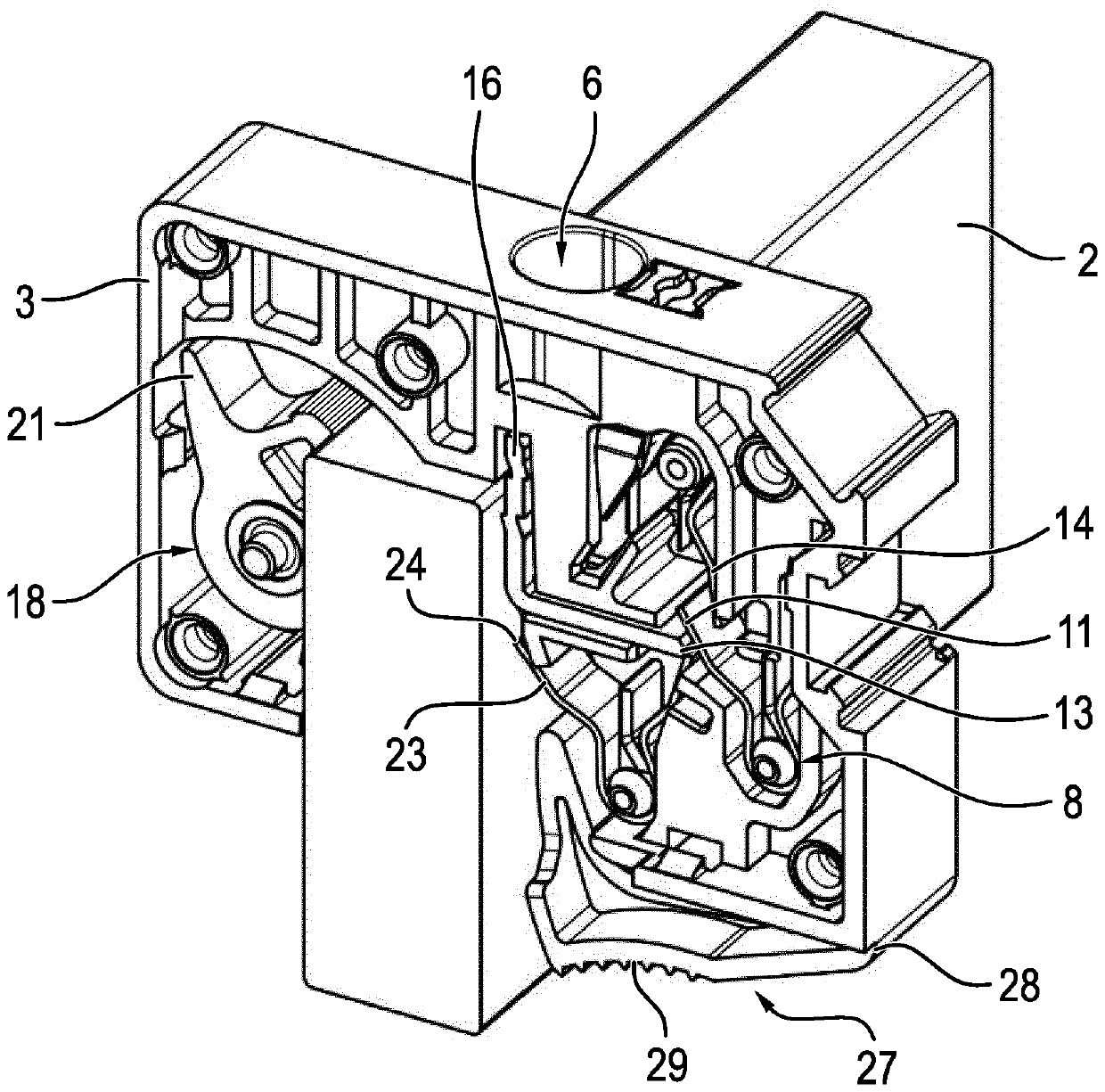
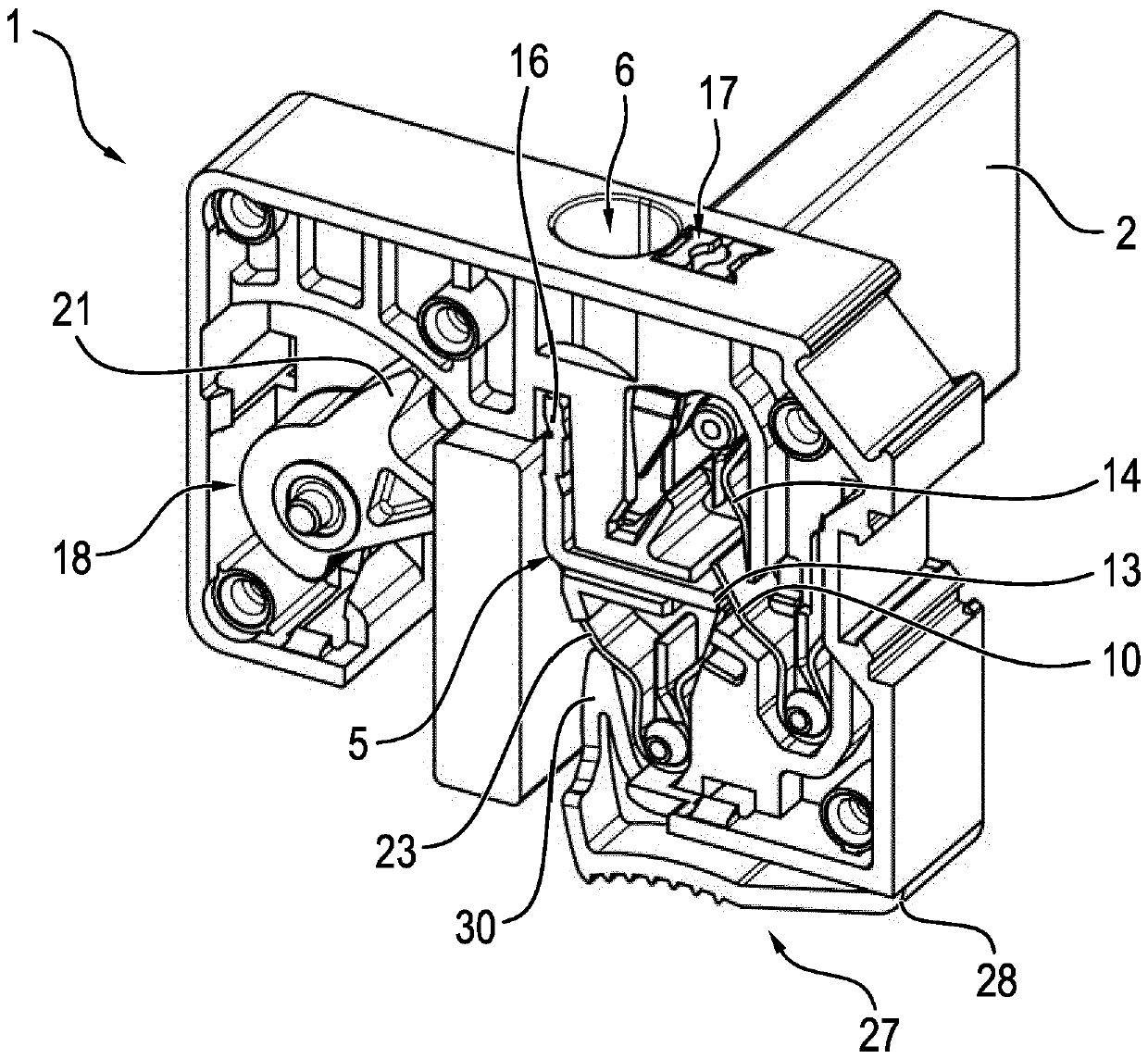
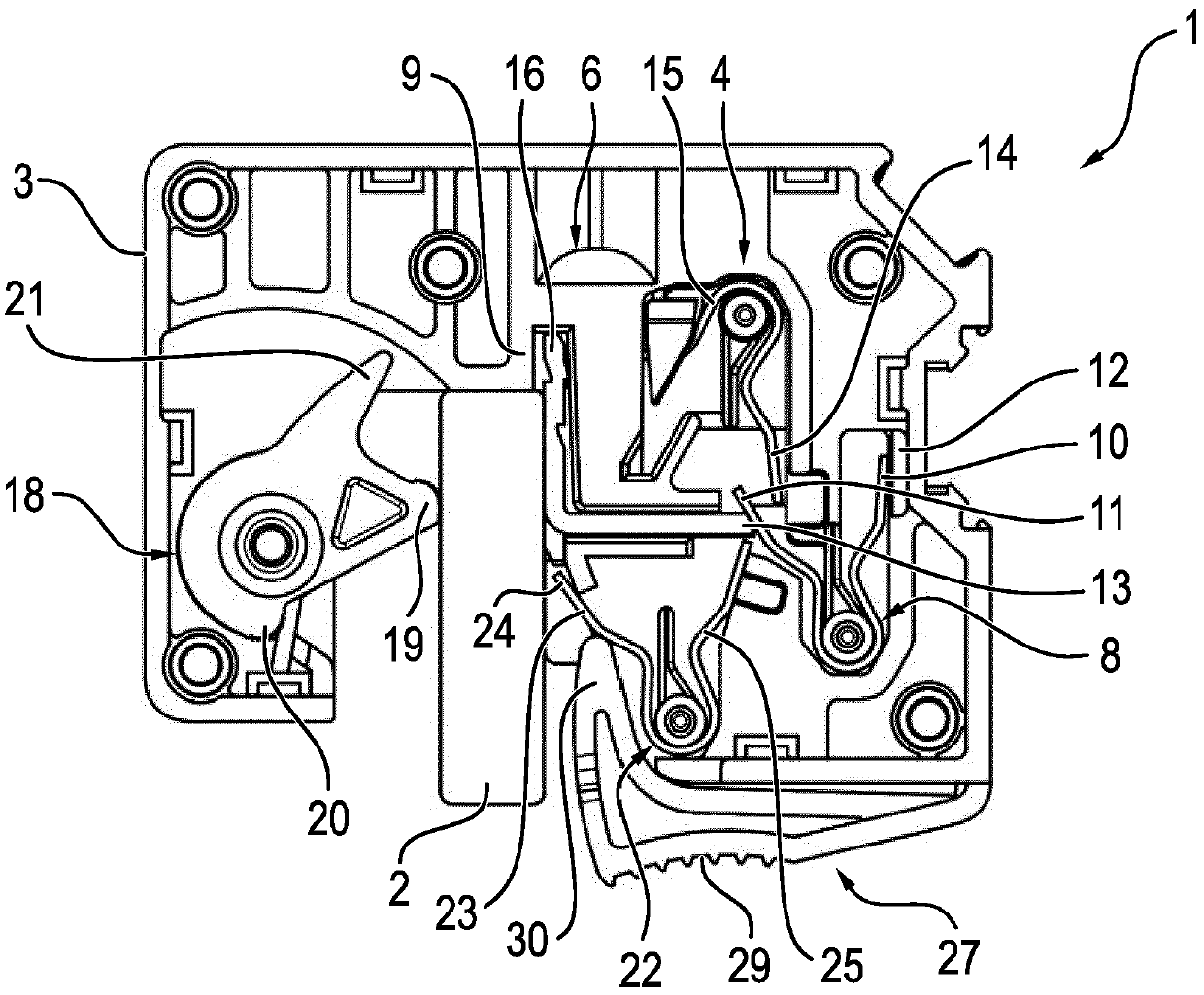
[0023] FIG. 1 shows a preferred exemplary embodiment of a connection terminal 1 according to the invention for connecting electrical conductors (not shown here) to a busbar 2 . 1 shows a connection terminal 1 without a busbar 2, while FIGS. 2, 3 and 4 show a connection terminal 1 with two busbars 2 of different thickness, i. row 2 (Figure 2 and Figure 4) and once with a thicker second busbar 2 (Figure 3). FIG. 4 shows a connection terminal 1 with a thinner busbar 2 according to FIG. Plug in direction A to remove the connecting terminal 1 from the bus bar 2.

[0024] The terminal 1 according to the invention has a housing 3 in which a conductor connection element 4 in the form of a helical torsion spring and an L-shaped current bar 5 are arranged. In order to introduce the wires to be connected into the clamping point, wire insertion openings 6 are formed in the housing 3 . Furthermore, the housing 3 , usually made of plastic, has a busbar receptacle 7 which is open on one s...


PUM


Abstract

The invention illustrates and describes a connection terminal (1) for connecting an electrical conductor to a busbar (2), said connection terminal having a housing (3), comprising a conductor connection element (4) and comprising a current bar (5), wherein the housing (3) has a conductor insertion opening (6) for inserting the electrical conductor and has a busbar holder (7) for holding the busbar(2), wherein the current bar (5) is mounted in a displaceable manner in the housing (3), and wherein a spring element (8) is arranged in the housing (3) in such a way that the spring element (8) subjects the current bar (5) to the action of a force in the direction of the busbar holder (7), so that a conductor which is connected by means of the conductor connection element (4) is electrically conductively connected to a busbar (2), which is arranged in the busbar holder (7), by means of the current bar (5).

Description

technical field [0001] The invention relates to a connection terminal for connecting electrical conductors to busbars. Background technique [0002] Electrical connection terminals are known in various embodiments. The connection terminal can, for example, connect the conductors to the terminal block as a so-called printed terminal or, as in the scope of this patent application, can be designed for connecting electrical conductors to busbars. As an example of the use of such connection terminals, shield connection terminals have been known for many years, with which the cable shields of generally multi-core cables can be connected to busbars. Such shielding terminals are known from Phoenix Contact GmbH & Co. KG in the category "Series Terminals (Reihenklemmen) CLIPLINE 1 2011", pages 546-548. [0003] Known shielding terminals have an approximately U-shaped metal connecting body, wherein slots are formed in the two legs of the connecting body, by means of which the shieldi...

Claims


Application Information

Patent Timeline
IPC IPC(8): H01R9/22
CPCH01R9/22H01R9/2675H01R25/14H01R4/48365
Inventor M.格布哈特
Owner PHOENIX CONTACT GMBH & CO KG
Why Eureka
Try Eureka