Supercharge Your Innovation With Domain-Expert AI Agents!

Vacuum cleaner with filter element

A filter and vacuum cleaner technology, which is applied in the direction of vacuum cleaners, cleaning filter devices, suction filters, etc., to achieve the effect of increasing the flow speed

Active Publication Date: 2021-06-29
VORWERK & CO INTERHOLDING GMBH
View PDF10 Cites 0 Cited by
  • Summary
  • Abstract
  • Description
  • Claims
  • Application Information

AI Technical Summary

Problems solved by technology

[0007] Although this type of construction is possible in the prior art, it requires certain dimensions of the suction chamber and thus also of the vacuum cleaner.

Method used


Image

  • Vacuum cleaner with filter element
  • Vacuum cleaner with filter element
  • Vacuum cleaner with filter element

Examples


Embodiment Construction

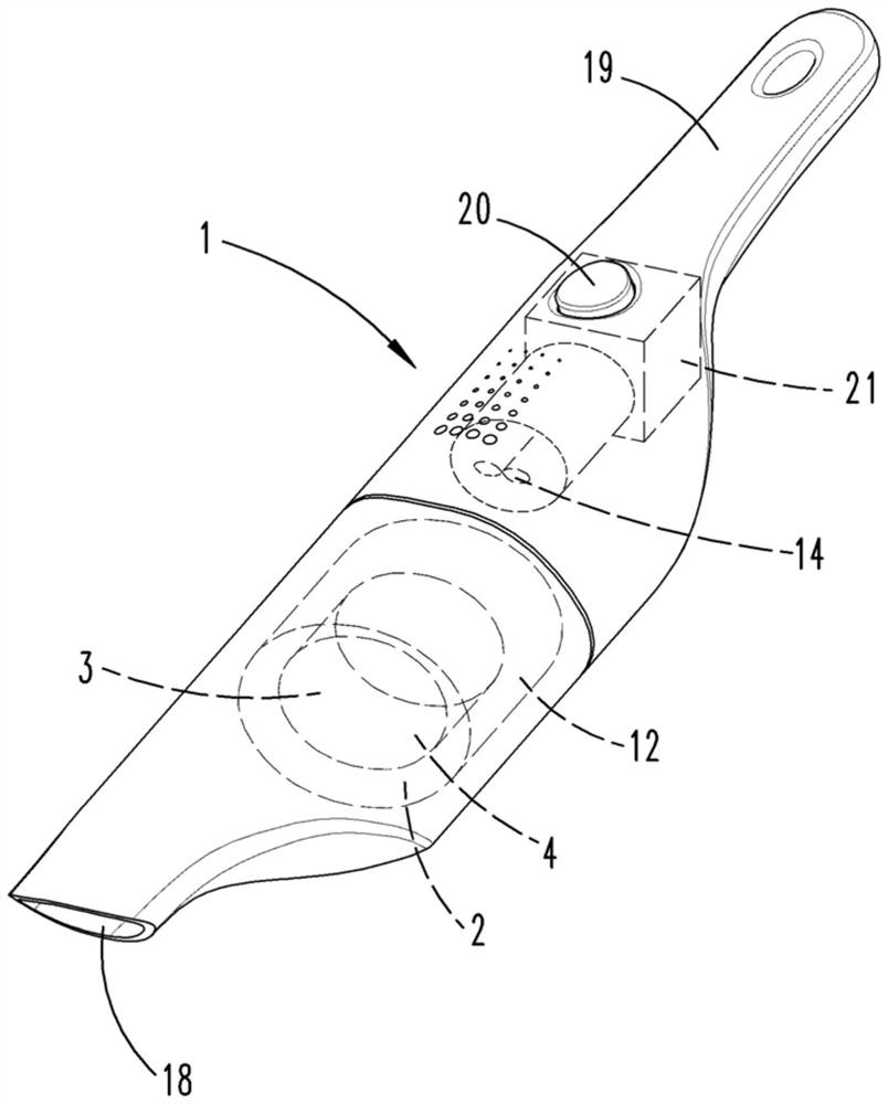
[0030] figure 1 A vacuum cleaner is shown, which is here designed as a hand-held battery vacuum cleaner. The vacuum cleaner 1 has a housing with a suction nozzle 18 and a handle 19 by means of which a user can hold the vacuum cleaner 1 in his hand and guide the vacuum cleaner. Arranged on the handle 19 is a switch 20 for switching on and off a motor 21 which drives the fan 14 . The vacuum cleaner 1 also has a filter chamber 12 with a filter element 4 which is here designed as a regenerable long-term filter. The filter element 4 separates the filter chamber 12 into a clean air chamber 2 and a suction chamber 3 . During normal filter operation of the vacuum cleaner 1 , the fan 14 sucks in air and the suctioned material enters the suctioned material chamber 3 through the suction nozzle 18 . The aspirated suction remains in the suction chamber 3 so that only cleaned air can reach the fan 14 .

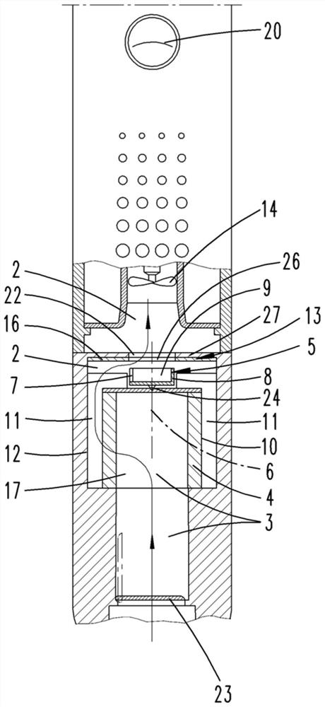
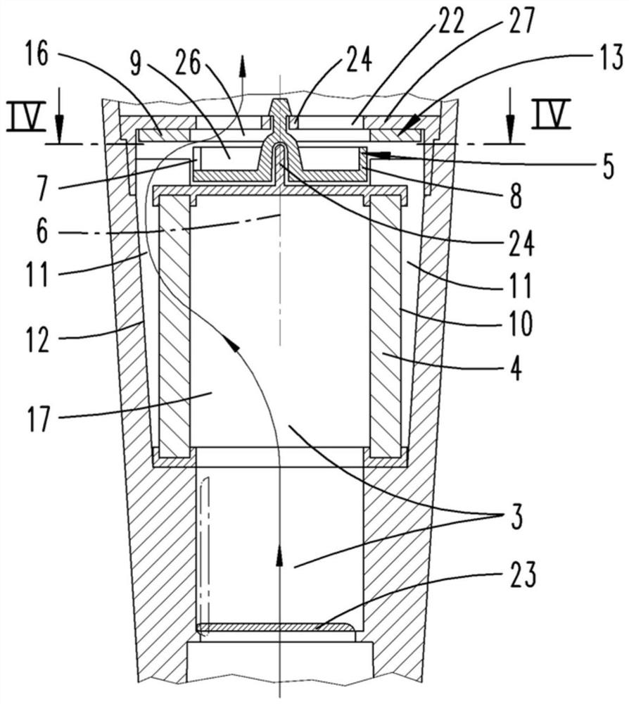
[0031] During suction operation, the suction product in the suction product chamber...


PUM


Abstract

The invention relates to a vacuum cleaner (1) with a filter element (4) separating a clean air chamber (2) from a suction chamber (3), said filter element (4) being filtered during filtering operation The air flows from the suction chamber (3) in the direction of the clean air chamber (2) and the cleaned air flows from the clean air chamber (2) to the suction chamber (3) during regenerative operation In order to release the suction on the side of the filter element (4) facing the suction chamber (3). In order to be able to manufacture the vacuum cleaner (1) with the smallest possible installation space, it is proposed here that the filter element (4) forms at least one partial volume of the clean air chamber (2) that collects suction, and that The filter element (4) is equipped inside the clean air chamber (2) with an air distribution device (5) designed to divert the clean air flow to the filter in a time-varying manner in different partitions of element (4).

Description

technical field [0001] The invention relates to a vacuum cleaner, in particular a hand-held battery vacuum cleaner, with a filter element separating a cleaning air chamber from a suction chamber, which filter element is drawn from the suction chamber by air to be cleaned during filtering operation. direction to the clean air chamber, and in regeneration mode the cleaned air flow flows from the clean air chamber to the suction chamber so that the filter element faces the suction chamber The aspirate on the side of the cavity comes loose. [0002] The invention also relates to a method for operating a vacuum cleaner, wherein the filter element separating the clean air chamber from the suction chamber is penetrated by the air to be cleaned from the direction of the suction chamber to the clean air chamber during filtering operation. During regeneration operation, the cleaned air flow flows through from the direction of the clean air chamber to the direction of the suction chambe...

Claims


Application Information

Patent Timeline
Patent Type & Authority Patents(China)
IPC IPC(8): A47L9/10
CPCA47L9/10A47L5/24A47L9/127A47L9/20A47L9/2857
Inventor M.塞尔奈奇
Owner VORWERK & CO INTERHOLDING GMBH
Features
  • R&D
  • Intellectual Property
  • Life Sciences
  • Materials
  • Tech Scout
  • Unparalleled Data Quality
  • Higher Quality Content
  • 60% Fewer Hallucinations
Learn More