Cantilever crane

A cantilever crane and cantilever technology, applied in the field of cantilever cranes, can solve the problems of long cantilever, bulky, unable to achieve self-locking, etc., and achieve the effect of locking safety and preventing collision

Pending Publication Date: 2018-04-17
浙江邦博机械有限公司
View PDF1 Cites 3 Cited by
  • Summary
  • Abstract
  • Description
  • Claims
  • Application Information

AI Technical Summary

Problems solved by technology

The split-column cantilever crane with the above-mentioned structure, although its weight has been reduced and its shape has been reduced, is still relatively heavy and cannot realize self-locking, and the cantilever is long, and the self-gravity of the heavy object generates a large force through the cantilever. moment, which exerts great pressure on the mandrel

Method used


Image

  • Cantilever crane
  • Cantilever crane
  • Cantilever crane

Examples


Embodiment

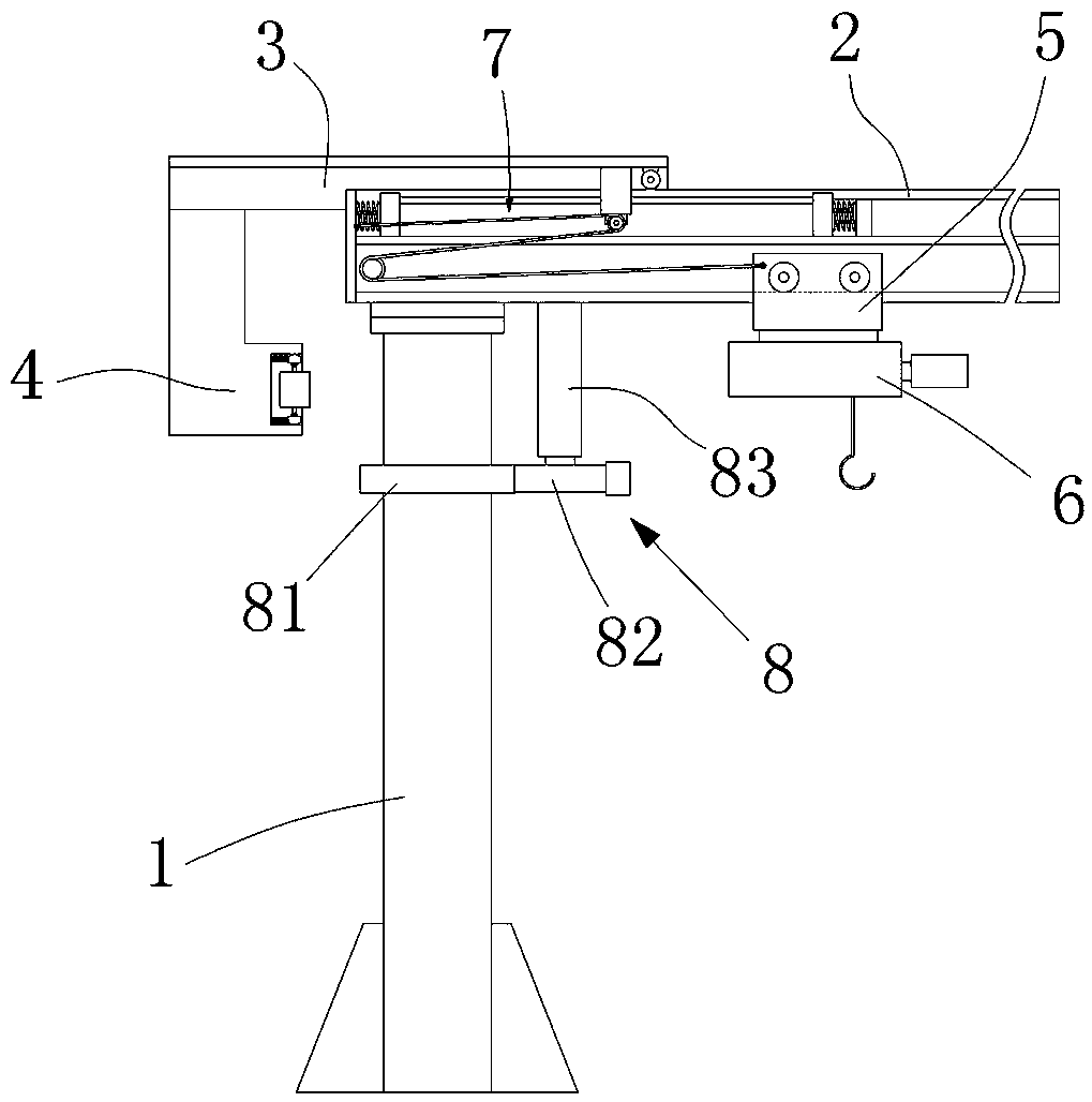
[0022] Example: such as Figure 1-5 As shown, a cantilever crane includes a column 1, a boom, a mobile trolley 5 moving along the boom and an electric hoist 6 mounted on the mobile trolley 5, and the boom is mounted on the column 1 through a rotating support. And rotate relative to the column 1. The rotation support includes an upper support plate arranged at the end of the boom and a lower support plate arranged on the column 1, and the upper and lower support plates are connected by a rotating shaft and a bearing.

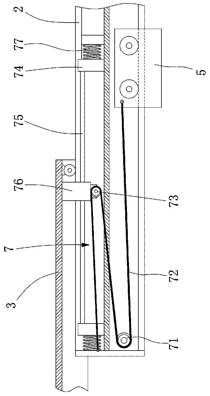
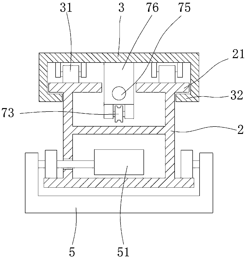
[0023] Such as figure 1 , figure 2 and image 3 As shown, the boom is a telescopic structure, including a boom 2 and a balance arm 3. One end of the boom 2 is rotatably mounted on the column 1, and the balance arm 3 is slidably mounted on the boom 2 and moves along the boom 2. The length direction of moving, the driving mechanism 7 that drives the balance arm 3 to move is arranged between the moving trolley 5 and the balance arm 3, so that the balance arm 3 ...


PUM


Abstract

The invention relates to a cantilever crane, which includes a column, a boom, a mobile trolley moving along the boom, and an electric hoist installed on the trolley. The boom is a telescopic structure, including a cantilever and a balance arm. One end is rotatably mounted on the column, the balance arm is slidably mounted on the cantilever and moves along the length of the cantilever, and a driving mechanism is provided between the moving trolley and the balance arm to drive the movement of the balance arm , so that the balance arm and the mobile trolley move synchronously and in opposite directions, and the column is also provided with a locking device for locking the position of the boom. The invention locks the rotation angle of the cantilever through the locking device on the column, effectively preventing heavy objects from colliding with surrounding objects, and by setting the telescopic boom, the centrifugal effect generated when the boom rotates is reduced, making the locking safer and more stable .

Description

technical field [0001] The invention relates to the technical field of cranes, in particular to a cantilever crane. Background technique [0002] With the continuous development of the economy, cantilever cranes have been widely used in economic construction. The currently used cantilever crane has a relatively large structure size and weight. When lifting an object in a small space, it is easy to collide with the surroundings due to the swing of the cantilever. In addition, the use environment of the existing cantilever cranes is mostly on the ground or at a position with a low height from the ground. The cantilever is rotated by pulling the suspension ring at the front end of the cantilever. [0003] For example: the Chinese utility model with the application number 201120435809.9 discloses a split-column cantilever crane, including a column and a rotating arm. The rotating arm is provided with a lifting device, and the tail end of the rotating arm is installed on the upp...

Claims


Application Information

Patent Timeline
Patent Type & Authority Applications(China)
IPC IPC(8): B66C23/04B66C23/16B66C23/76B66C23/84B66C23/94
CPCB66C23/005B66C23/04B66C23/163B66C23/76B66C23/84B66C23/94
Inventor 朱晓翔
Owner 浙江邦博机械有限公司
Why Eureka
Try Eureka