Automated electrolytic tank

A technology of electrolytic cell and movable plate, which is applied in the direction of electrolytic process, electrolytic components, cells, etc. It can solve the problems of inability to directly adjust the pole distance of the electrolytic cell, inconvenient electrolytic reaction, and unsatisfactory electrolytic reaction efficiency of the electrolytic cell, etc., to achieve stable rotation, The effect of improving efficiency and stabilizing support

Inactive Publication Date: 2018-04-17
BINZHOU MEDICAL COLLEGE
View PDF9 Cites 1 Cited by
  • Summary
  • Abstract
  • Description
  • Claims
  • Application Information

AI Technical Summary

Problems solved by technology

[0005] Aiming at the deficiencies of the prior art, the present invention provides an automatic electrolytic cell, which solves the problem that the cathode rod and the anode rod inside the traditional electrolytic cell are usually directly fixed inside the electrolytic cell during use, and the temperature in the electrolytic cell cannot be directly adjusted. Therefore, the efficiency of the electrolytic reaction inside the electrolytic cell may not be ideal, which brings inconvenience to people when using the electrolytic cell for electrolytic reaction.

Method used


Image

  • Automated electrolytic tank
  • Automated electrolytic tank

Examples


Embodiment Construction

[0021] The following will clearly and completely describe the technical solutions in the embodiments of the present invention with reference to the accompanying drawings in the embodiments of the present invention. Obviously, the described embodiments are only some, not all, embodiments of the present invention. Based on the embodiments of the present invention, all other embodiments obtained by persons of ordinary skill in the art without making creative efforts belong to the protection scope of the present invention.

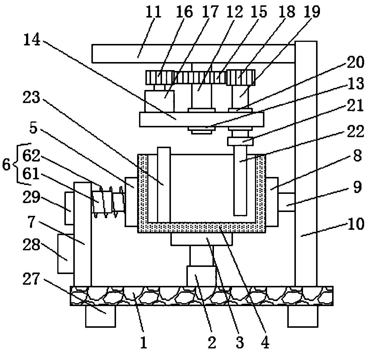
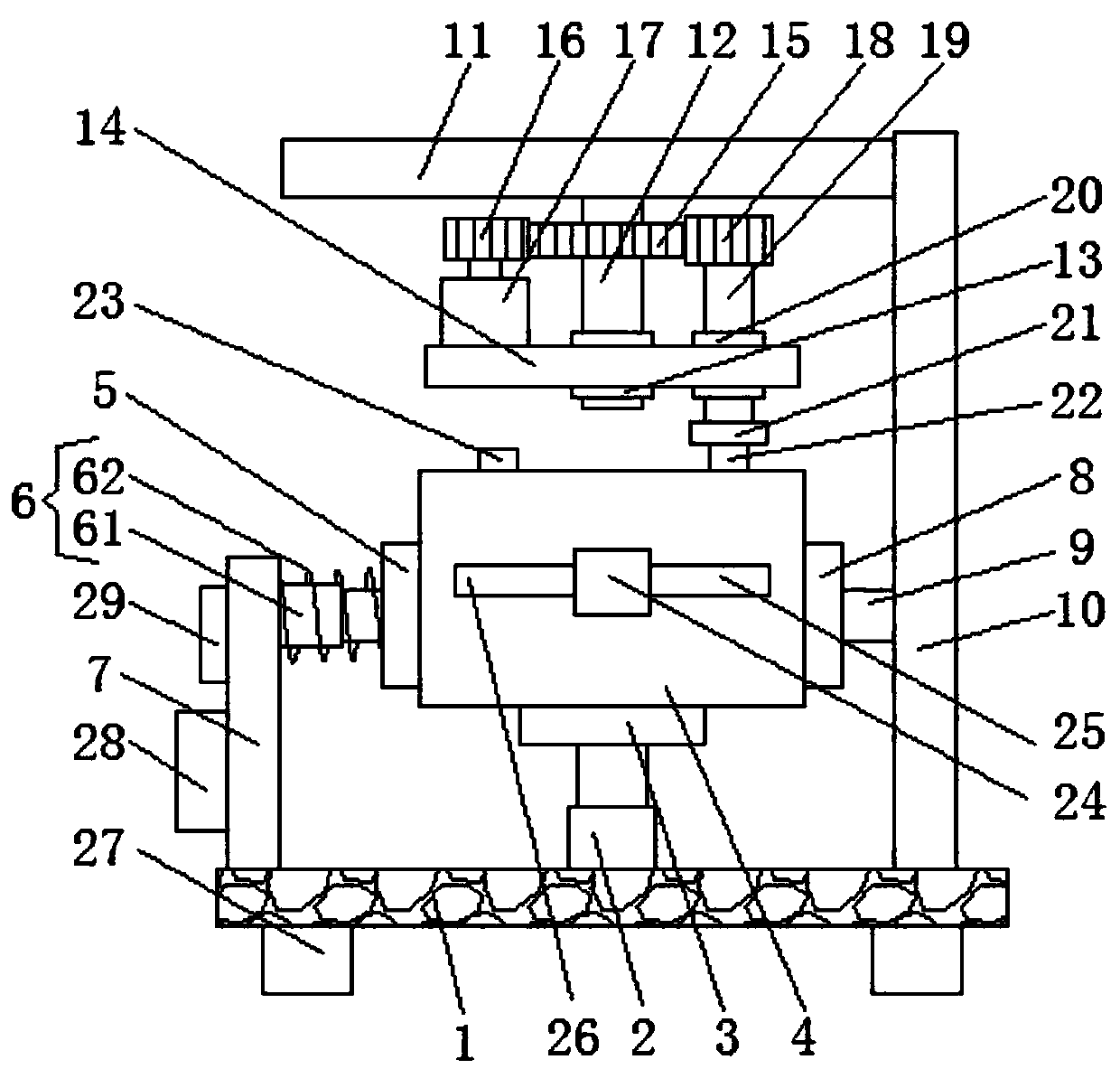
[0022] Such as Figure 1-2As shown, the present invention provides a technical solution: an automated electrolytic cell, including a base plate 1, the lower surface of the base plate 1 is fixedly connected with four support legs 27, and the four support legs 27 are respectively located at the four corners of the lower surface of the base plate 1 , by setting four supporting legs 27, the support of the base plate 1 can be made more stable, the shape of the base...


PUM


Abstract

The invention discloses an automated electrolytic tank, which comprises a base plate. An electric push rod is fixedly connected to the upper surface of the base plate. A first stripper plate is fixedly connected to the top of the electric push rod. The upper surface of the first stripper plate is in lap joint with the lower surface of the outer wall of the electrolytic tank body. A second stripperplate is in lap joint with the left side surface of the outer wall of the electrolytic tank body. according to the automated electrolytic tank, by arranging a motor, an output shaft of the motor rotates to drive a second gear to rotate; the second gear rotates on the surface of a first gear to drive a movable plate to rotate around a first rotating shaft; a third gear rotates to drive a second rotating shaft to rotate; the second rotating shaft drives an anode bar to rotate through a connecting block, and the anode bar also can rotate inside the electrolytic tank body while rotating itself soas to directly regulate the distance between the anode bar anode bar and a cathode bar. Then, efficiency of an electrolytic reaction inside the electrolytic tank body is raised. The automated electrolytic tank brings convenience for people to use the electrolytic tank to carry out an electrolytic reaction.

Description

technical field [0001] The invention relates to the technical field of electrolysis equipment, in particular to an automatic electrolysis cell. Background technique [0002] Electrolysis is a process in which an electric current is passed through an electrolyte solution or a molten electrolyte to cause a redox reaction on the cathode and anode. The electrolysis process can occur when an electrochemical cell is applied with a DC voltage. The process of producing synthetic high-purity substances of chemicals and treating the surface of materials by using the electrochemical reaction that occurs at the interface between the electrode as an electron conductor and the electrolyte as an ion conductor. When energized, the cations in the electrolyte move to the cathode, absorb electrons, undergo reduction, and generate new substances; the anions in the electrolyte move to the anode, release electrons, undergo oxidation, and generate new substances. [0003] The pole distance is not...

Claims


Application Information

Patent Timeline
Patent Type & Authority Applications(China)
IPC IPC(8): C25C7/00
CPCC25C7/00C25C7/005
Inventor 闫鹏秦丹李光仲
Owner BINZHOU MEDICAL COLLEGE
Why Eureka
Try Eureka