Device for preventing accumulated snow on cable

A cable and snow accumulation technology, which is applied in the field of electric power maintenance, can solve the problems of high load-bearing cost of utility poles, reduced snow protection effect, and limited rotation angle of rolling components, etc.

Active Publication Date: 2018-04-17
杭州东南吉通网络有限公司
View PDF4 Cites 6 Cited by
  • Summary
  • Abstract
  • Description
  • Claims
  • Application Information

AI Technical Summary

Problems solved by technology

However, the scope of this snow prevention method is the length of the entire hollow tube and the snow removal pole. In order to achieve the purpose of snow prevention, the total length or the sum of the lengths of the multiple snow protection devices will be close to the distance between the two poles, increasing the distance between the poles. The weight and cost are high; after the cable is installed, the middle part of the utility pole will sink due to its own weight. At this time, the cable is arc-shaped, and the rotation angle of the rolling assembly will be limited at this time, reducing the snow-proof effect

Method used


Image

  • Device for preventing accumulated snow on cable
  • Device for preventing accumulated snow on cable
  • Device for preventing accumulated snow on cable

Examples


Embodiment 1

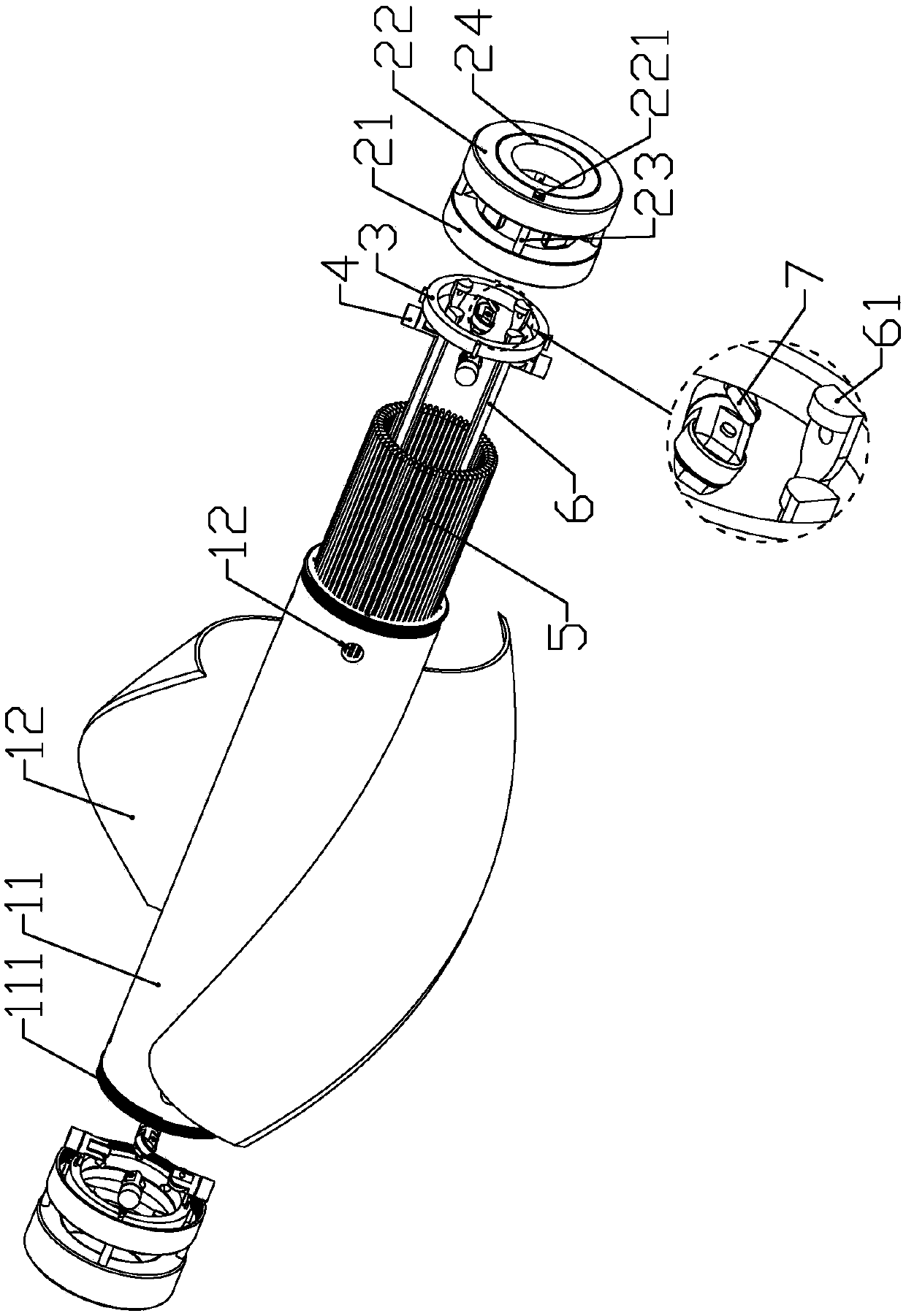
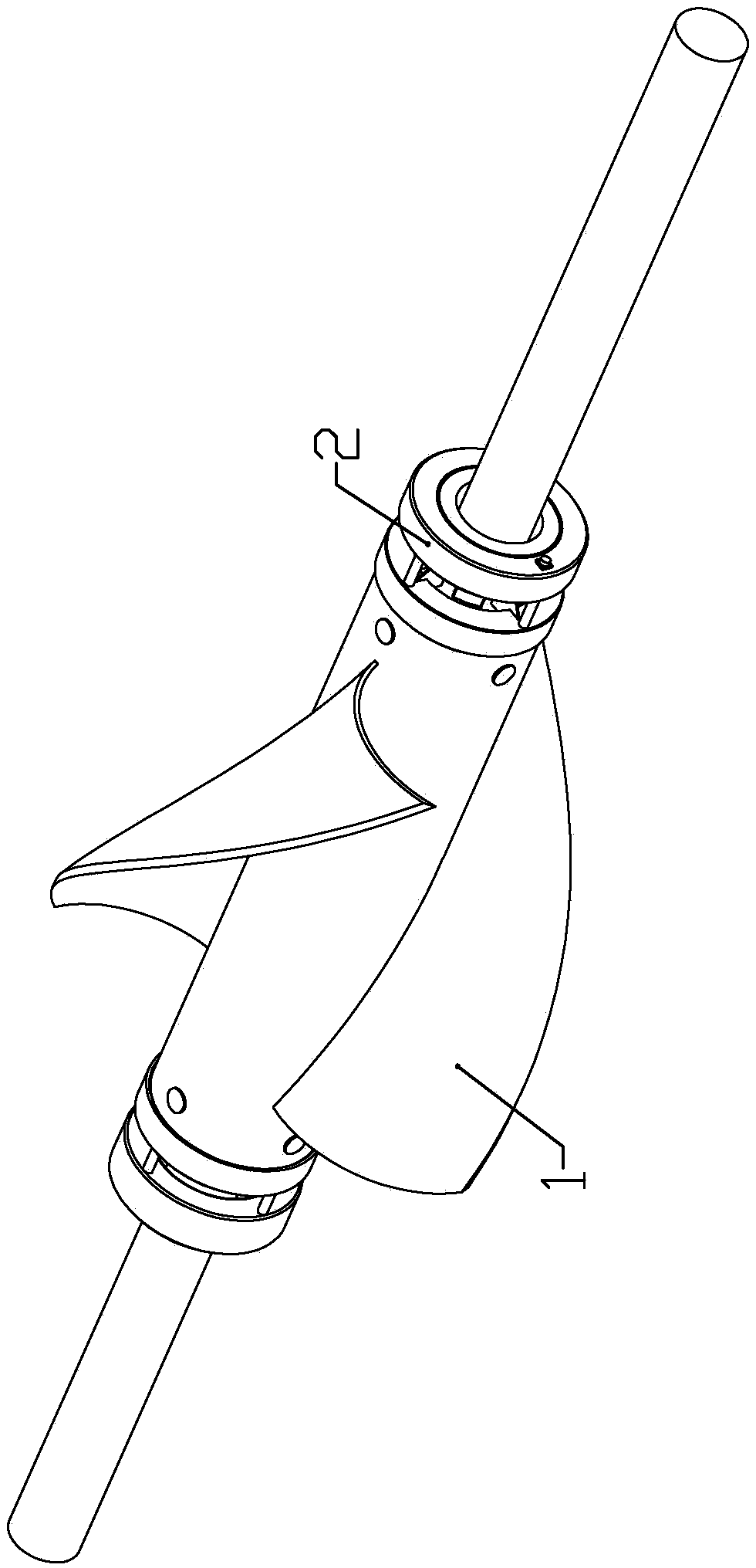
[0029] according to Figure 1 to Figure 6 As shown, this embodiment is a device for preventing snow accumulation on cables, which includes a windward cylinder 1, two end caps 2 fixedly installed at both ends of the windward cylinder, and two circular rings arranged at both ends of the inner wall of the windward cylinder. A sliding ring 3, a plurality of long connecting rods 6 connected between the two sliding rings.

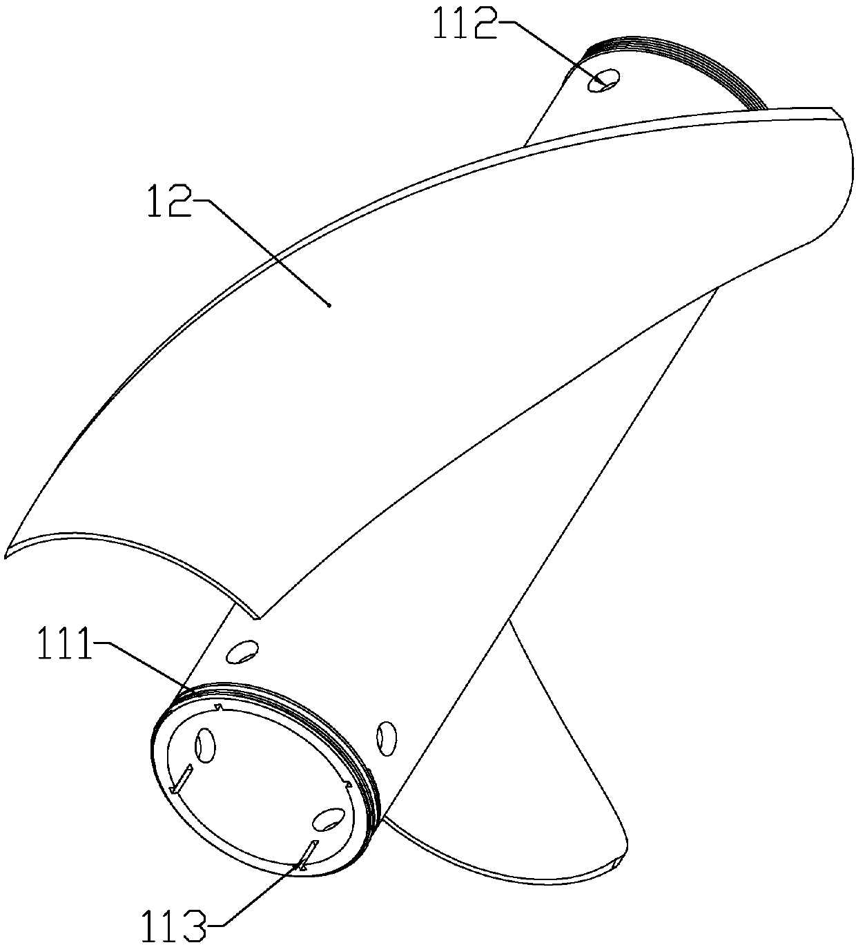
[0030] The windward cylinder includes a cylindrical body 11 that is sheathed on the cable; the outer wall of the windward cylinder is symmetrically formed with two spiral blades 12; the cross section of the two spiral blades forms an S shape (along the The radial section of the above-mentioned windward tube); it can be known from the S-type vertical wind generator that under the action of wind force, the force on the concave surface of the windward tube is greater than that on the convex surface, so that the windward tube can always Rotate in one direction.

[...

Embodiment 2

[0045] combine Figure 7 As shown, the difference between this embodiment and Embodiment 1 is that: the outer end of the contact end is equidistantly equipped with a plurality of contact switches 221 arranged in parallel; the outer end of the contact end is provided with an annular contact plate 25; the contact A plurality of springs 26 are fixedly connected between the end and the contact plate.

[0046] By providing a plurality of contact switches, when the contact disk touches an obstacle, the contact disk presses the contact switch to make the linear motor work, thereby changing the moving direction of the wind cylinder.

[0047] The contact switch is triggered indirectly by setting the contact plate, which avoids the situation that the single contact switch cannot effectively touch the obstacle, or the wind cylinder cannot continue to rotate due to the protrusion of the contact switch.

Embodiment 3

[0049] This embodiment makes the following improvements on the basis of embodiment 1 or embodiment 2: each section of cable is fixedly connected with a plurality of limit disks perpendicular to the cable, and the radius of the limit disk is larger than the distance from the contact switch to the cable. distance. For the convenience of installation, the limiting disc is divided into two halves and fixedly connected to the cable.


PUM


Abstract

The invention belongs to the field of power maintenance and particularly relates to a device for preventing accumulated snow on a cable. The device comprises a windward drum sleeving the cable, two end covers, two circular sliding rings and a plurality of long connecting rods connected between the two sliding rings, wherein the two end covers are fixedly arranged at two ends of the windward drum;and the two circular sliding rings are arranged at two ends of an inner wall of the windward drum. The device is capable of making the accumulated snow on fan blades fall off in the rotating process and simultaneously scraping away the accumulated snow on the cable in the movement process of the windward drum; and the rotating and moving speeds of the windward drum can be increased under the action of wind, so that the snow removal efficiency is improved.

Description

technical field [0001] The invention belongs to the field of electric power maintenance, and in particular relates to a device for preventing snow accumulation on cables. Background technique [0002] With the increase of power projects, more and more power maintenance work is required, especially in areas with more rainy and snowy weather in winter, it often occurs that the cables are damaged or even broken due to excessive snow accumulation on the cables, thereby causing power interruptions, and The road to maintenance cables is often not smooth during heavy snow, so that maintenance work cannot be carried out in time, and the snow removal method currently adopted is inefficient. [0003] The application number is 201610751909.x, which discloses a rotary electric wire snow protection device, which uses different weights of snow on three snow packs to make the rolling assembly rotate, so that the snow on the snow packs falls. However, the scope of this snow prevention meth...

Claims


Application Information

Patent Timeline
Patent Type & Authority Applications(China)
IPC IPC(8): H02G7/16
CPCH02G7/16
Inventor 黄文佳
Owner 杭州东南吉通网络有限公司
Why Eureka
Try Eureka