Systems and methods for heart valve therapy

A heart valve, valve technology, applied in the direction of heart valve, valve annulus, medical science, etc., to achieve the effect of less invasion

Active Publication Date: 2018-04-17
CAISSON INT LLC
View PDF6 Cites 3 Cited by
  • Summary
  • Abstract
  • Description
  • Claims
  • Application Information

AI Technical Summary

Problems solved by technology

Thus, in some cases, a prosthetic valve system that deteriorates LV geome

Method used


Image

  • Systems and methods for heart valve therapy
  • Systems and methods for heart valve therapy
  • Systems and methods for heart valve therapy

Examples


Embodiment Construction

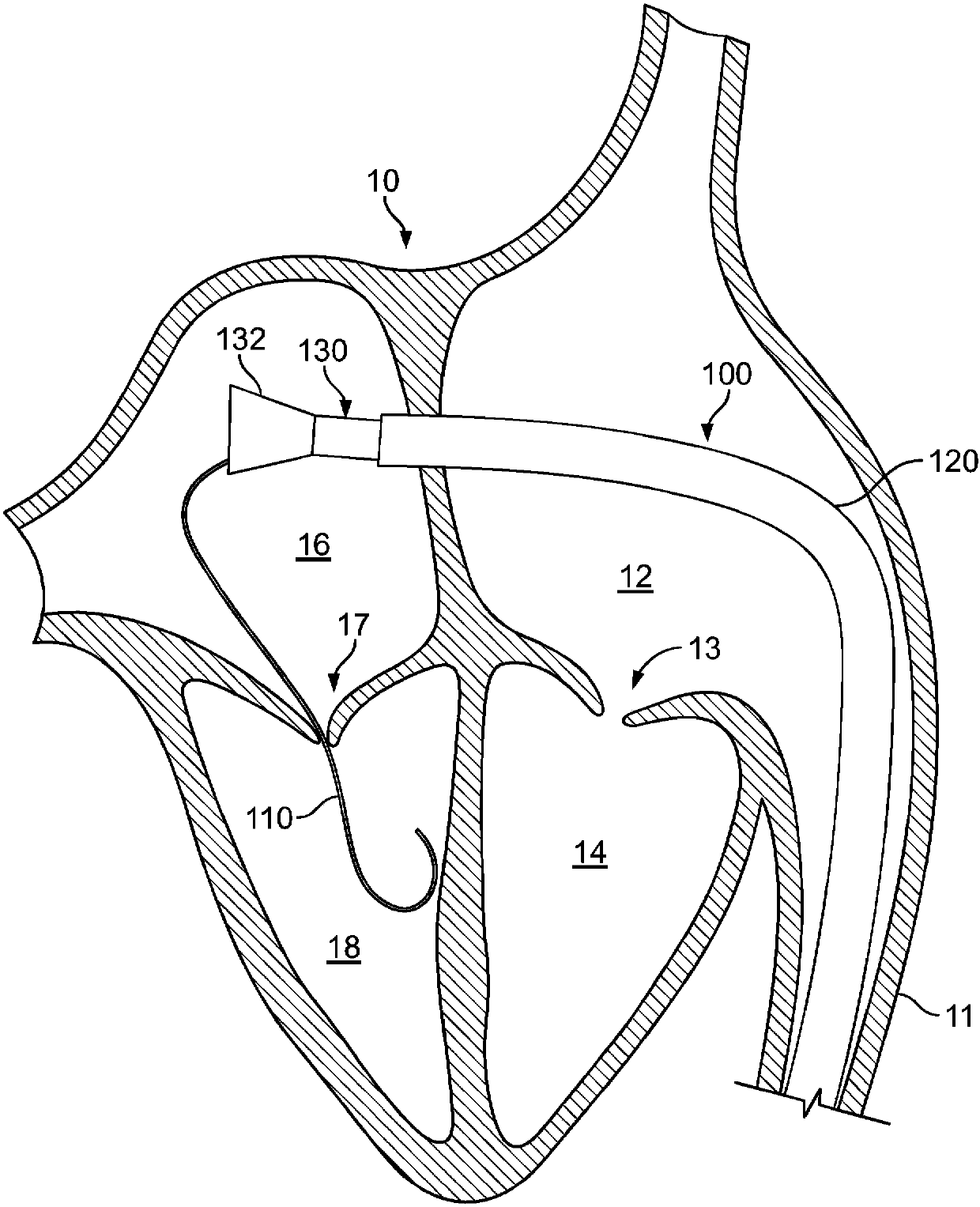
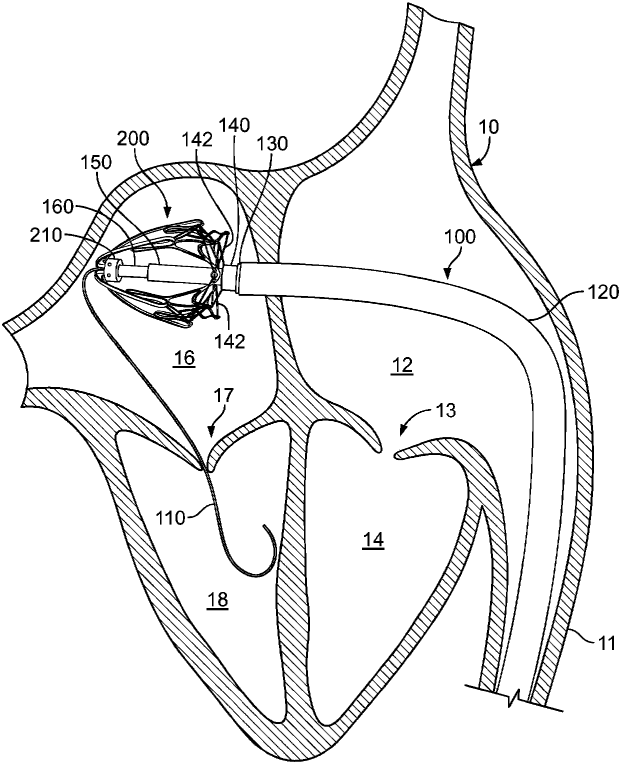
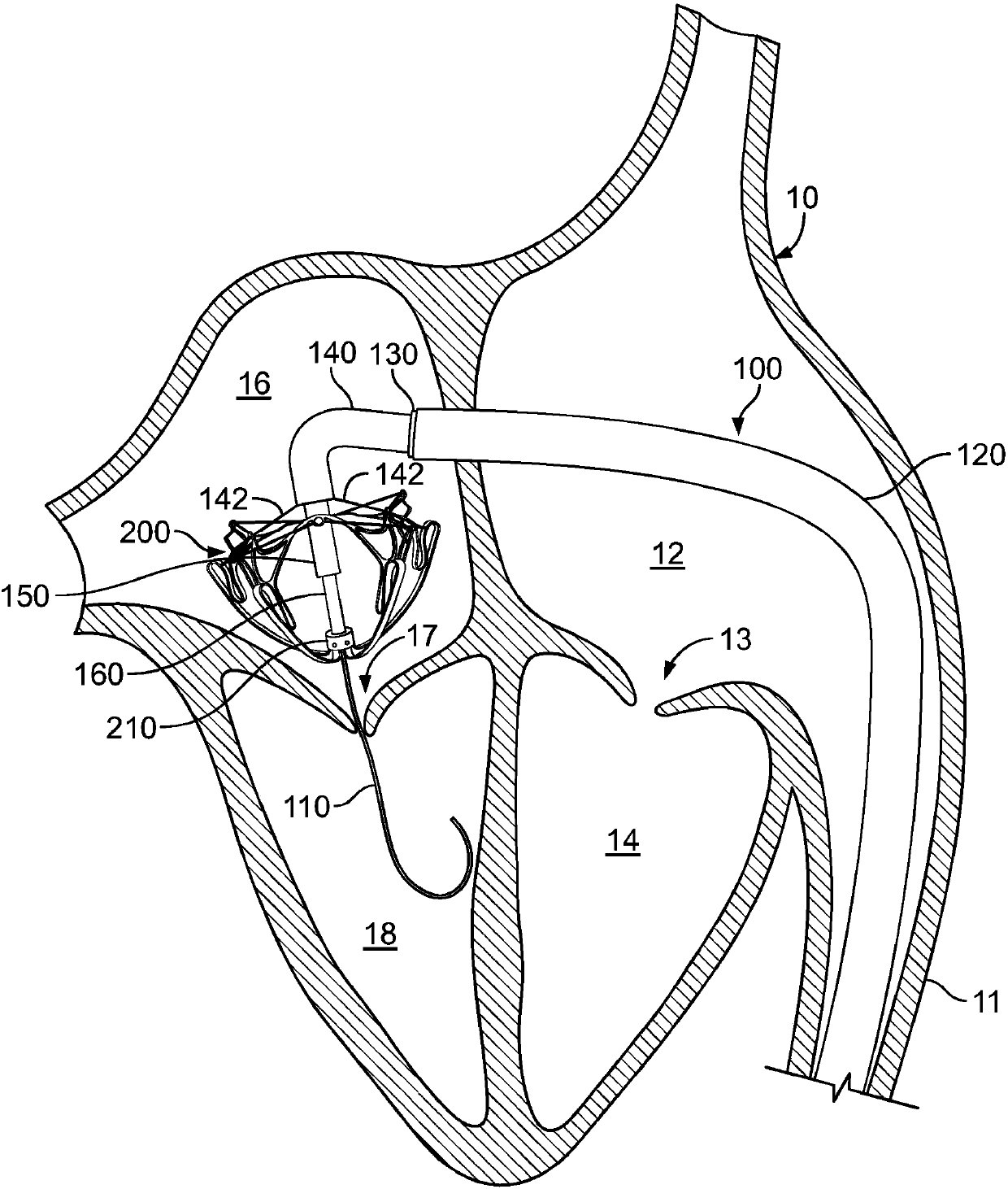
[0069] The present disclosure describes embodiments of a prosthetic heart valve system, such as a prosthetic mitral valve system, and transcatheter systems and methods for implanting a prosthetic heart valve system. In certain embodiments, the prosthetic mitral valve system can be deployed to interface with and anchor cooperatively with the natural anatomy of the mitral valve (and optionally, to allow the natural two The chordae of the cusp leaflets continue to function in a natural way, even after the anchoring member is deployed). A prosthetic mitral valve system as used herein can be deployed to interface with native mitral valve structure to form a fluid seal, thereby minimizing post-implantation MR and paravalvular leakage. As described in more detail below, Figure 1 to Figure 17 and Figure 39 to Figure 43 Transcatheter mitral valve delivery systems and methods are described whereby a prosthetic mitral valve system can be deployed to interface with and cooperate with ...


PUM


Abstract

Prosthetic mitral valves described herein can be deployed using a transcatheter mitral valve delivery system and technique to interface and anchor in cooperation with the anatomical structures of a native mitral valve. This document describes prosthetic heart valve designs that interface with native mitral valve structures to create a fluid seal, thereby minimizing mitral regurgitation and paravalvular leaks. This document also describes prosthetic heart valve designs and techniques to manage blood flow through the left ventricular outflow tract. In addition, this document describes prostheticheart valve designs and techniques that reduce the risk of interference between the prosthetic valves and chordae tendineae.

Description

[0001] Cross References to Related Applications [0002] This application claims the benefit of U.S. Provisional Patent Application No. 62 / 067,907, filed October 23, 2014; U.S. Provisional Patent Application No. 14 / 671,577, filed March 27, 2015; U.S. Provisional Patent Application No. 14 / 673,055 filed on March 30; and U.S. Provisional Patent Application No. 14 / 674,349 filed on March 31, 2015. The disclosure of the earlier application is considered a part of the disclosure of the present application and is incorporated by reference into the disclosure of the present application. technical field [0003] This document relates to prosthetic heart valves, such as prosthetic mitral valves, which may be implanted using transcatheter techniques. Background technique [0004] The long-term clinical effects of valvular regurgitation are considered an important cause of cardiovascular-related morbidity and mortality. Thus, for many therapies planned to treat the mitral valve, a majo...

Claims


Application Information

Patent Timeline
IPC IPC(8): A61B34/30
CPCA61F2/2448A61F2/2403A61F2/2409A61F2/2418A61F2/2436A61F2/2439A61F2230/0078A61F2250/0063
Inventor K·加内桑R·T·文卡塔苏布磊曼聂A·T·福斯伯格C·J·小施魏希T·J·莫笛尔E·O·马茨D·J·科隆
Owner CAISSON INT LLC
Why Eureka
Try Eureka