Flight flow field measurement device of bionic insect

A measuring device and technology of bionic insects, applied in the field of insect research, can solve the problems of difficult analysis and capture of flow field changes, and achieve the effects of reducing interference, improving propulsion efficiency, and improving accuracy

Inactive Publication Date: 2018-04-20
CHINA THREE GORGES UNIV
View PDF4 Cites 3 Cited by
  • Summary
  • Abstract
  • Description
  • Claims
  • Application Information

AI Technical Summary

Problems solved by technology

However, in real life, it is often difficult to capture the trajectories of insects with high-frequency flapping mo

Method used


Image

  • Flight flow field measurement device of bionic insect
  • Flight flow field measurement device of bionic insect

Examples


Embodiment Construction

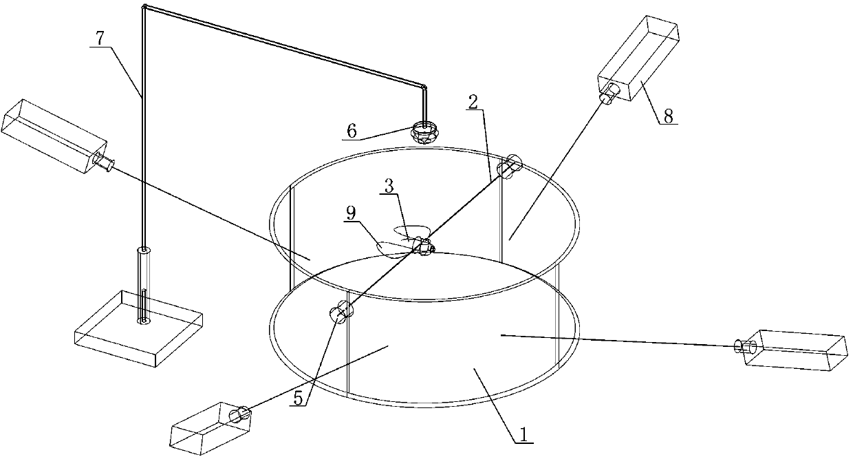
[0023] Such as figure 1 As shown, a bionic insect flight flow field measurement device includes a tank body 1 and a bracket body 7, a bionic insect 3 is provided in the tank body 1, a bionic wing 9 is provided on the bionic insect 3, and a bionic wing 9 is provided above the tank body 1 High-speed camera8.

[0024] A tracer particle layer or tracer particle group is arranged in the tank body 1 .

[0025] The tank body 1 is provided with a support rod or a support wire 2, and the bionic insect 3 is fixedly arranged on the support rod or the support wire 2.

[0026] Both ends of the support rod or support wire 2 are connected to the tank body wall of the tank body 1 through a fixing device 5 .

[0027] The support body 7 includes a base and one end of a telescopic rod fixed to the base, and the other end of the telescopic rod is provided with a lighting lamp 6 .

[0028] The illuminating lamp 6 is an LED lamp.

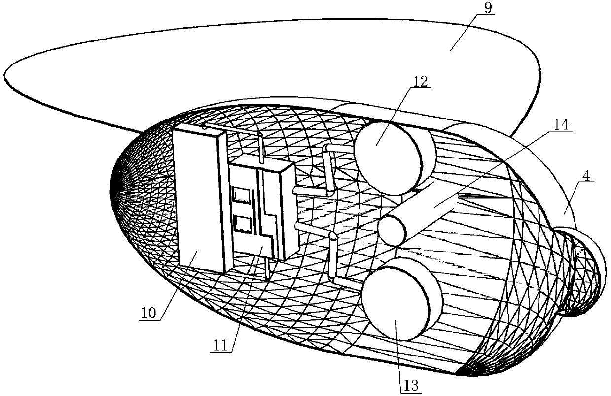
[0029] The bionic insect 3 includes a bionic insect body 4, a b...


PUM


Abstract

Discloses is a flight flow field measurement device of a bionic insect. The device includes a groove body and a support body; the groove body is internally provided with the bionic insect, bionic wings are arranged on the bionic insect, and a high-speed camera is arranged above the groove body. The device mainly aims at solving the technical problem that during research on flying insects, flow fields generated by wings during flight of the insects cannot be well obtained.

Description

technical field [0001] The invention belongs to the field of insect research, and in particular relates to a bionic insect flight flow field measuring device. Background technique [0002] Insects generate propulsion by flapping their wings when they fly, and the reaction force of the air fluid. The researchers found that its propulsion efficiency is much higher than that of current man-made aircraft. However, in real life, it is often difficult to capture the flight trajectory of insects with high-frequency flapping movements, and it is even more difficult to analyze the changes in the flow field generated by the wake during flight. [0003] The Chinese patent with the notification number CN2581325Y discloses a flapping wing device, which uses the resistance generated when the spring is twisted and the elastic force generated when it is restored to make the motor shaft rotate one circle, and the eccentric movement rate of the sleeve varies from slow to fast, resulting in b...

Claims


Application Information

Patent Timeline
IPC IPC(8): B64F5/60
CPCB64F5/60
Inventor 余英俊胡晓石小涛吴震尹入成张永年洪亮
Owner CHINA THREE GORGES UNIV
Why Eureka
Try Eureka