Ramming device for concrete-laid ground

A tamping device and concrete technology, which is applied in roads, road repairs, roads, etc., can solve labor-intensive and time-consuming problems

Inactive Publication Date: 2018-04-20
汤国忠
View PDF7 Cites 6 Cited by
  • Summary
  • Abstract
  • Description
  • Claims
  • Application Information

AI Technical Summary

Problems solved by technology

[0006] In order to overcome the shortcomings that many places are manually added to the concrete mixer for mixing, the present invention is very time-consuming and labor-intensive, and when the concrete is paved on the road, it needs to be sent to other machines for smoothing. The technical problem to be solved is to provide a concrete laying ground tamping device that can be automatically stirred, does not consume manpower, and can level the ground.

Method used


Image

  • Ramming device for concrete-laid ground
  • Ramming device for concrete-laid ground
  • Ramming device for concrete-laid ground

Examples


Embodiment 1

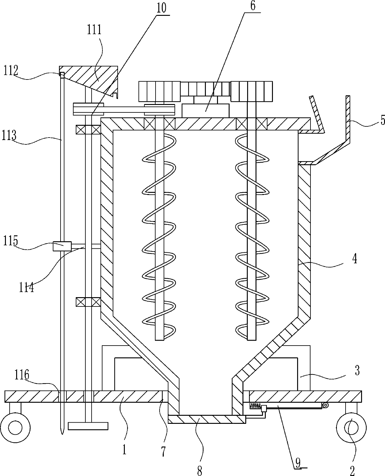
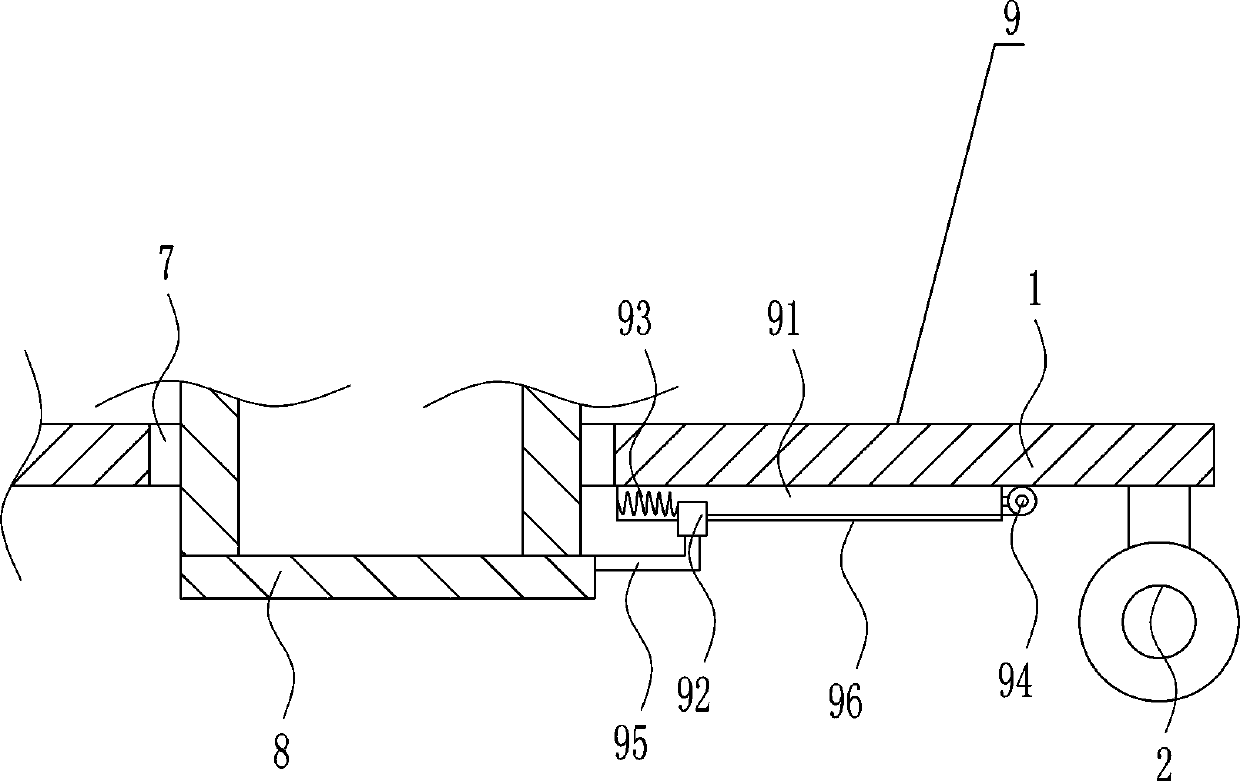
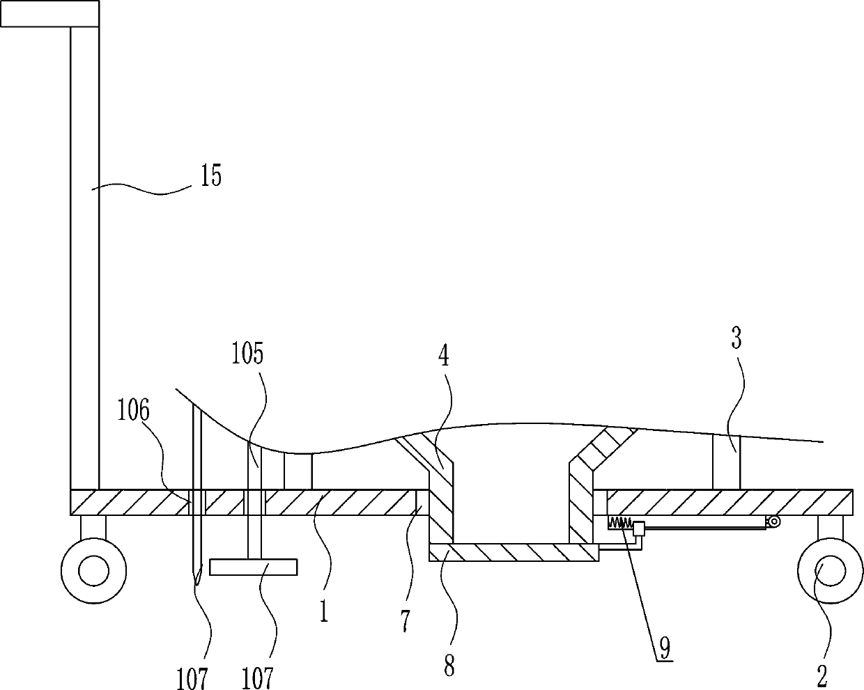
[0040] A concrete laying ground tamping device, such as Figure 1-9 As shown, it includes base plate 1, wheel 2, support rod 3, mixing box 4, feed hopper 5, stirring mechanism 6, baffle plate 8 and moving mechanism 9, the bottom of base plate 1 is provided with wheel 2, and the top of base plate 1 is provided with There is a mixing box 4, and left and right symmetrical support rods 3 are arranged on both sides of the bottom of the bottom plate 1, and the other end of the supporting rod 3 is connected with both sides of the mixing box 4, and a stirring mechanism 6 is arranged on the top of the mixing box 4, and the left side of the mixing box 4 There is a feed hopper 5 above the surface, a first through hole 7 is opened in the middle of the bottom plate 1, the stirring box 4 passes through the first through hole 7, a baffle plate 8 is provided under the stirring box 4, and a bottom plate 1 is provided on the right side of the bottom Mobile Mechanism9.

Embodiment 2

[0042] A concrete laying ground tamping device, such as Figure 1-9 As shown, it includes base plate 1, wheel 2, support rod 3, mixing box 4, feed hopper 5, stirring mechanism 6, baffle plate 8 and moving mechanism 9, the bottom of base plate 1 is provided with wheel 2, and the top of base plate 1 is provided with There is a mixing box 4, and left and right symmetrical support rods 3 are arranged on both sides of the bottom of the bottom plate 1, and the other end of the supporting rod 3 is connected with both sides of the mixing box 4, and a stirring mechanism 6 is arranged on the top of the mixing box 4, and the left side of the mixing box 4 There is a feed hopper 5 above the surface, a first through hole 7 is opened in the middle of the bottom plate 1, the stirring box 4 passes through the first through hole 7, a baffle plate 8 is provided under the stirring box 4, and a bottom plate 1 is provided on the right side of the bottom Mobile Mechanism9.

[0043] Stirring mechani...

Embodiment 3

[0045] A concrete laying ground tamping device, such as Figure 1-9 As shown, it includes base plate 1, wheel 2, support rod 3, mixing box 4, feed hopper 5, stirring mechanism 6, baffle plate 8 and moving mechanism 9, the bottom of base plate 1 is provided with wheel 2, and the top of base plate 1 is provided with There is a mixing box 4, and left and right symmetrical support rods 3 are arranged on both sides of the bottom of the bottom plate 1, and the other end of the supporting rod 3 is connected with both sides of the mixing box 4, and a stirring mechanism 6 is arranged on the top of the mixing box 4, and the left side of the mixing box 4 There is a feed hopper 5 above the surface, a first through hole 7 is opened in the middle of the bottom plate 1, the stirring box 4 passes through the first through hole 7, a baffle plate 8 is provided under the stirring box 4, and a bottom plate 1 is provided on the right side of the bottom Mobile Mechanism9.

[0046] Stirring mechani...


PUM


Abstract

The invention relates to a ramming device for the ground, in particular to a ramming device for the concrete-laid ground. According to the ramming device for the concrete-laid ground, automatic stirring can be conducted, manpower is not consumed, and the ground can further be leveled. The ramming device for the concrete-laid ground comprises a bottom plate, wheels, supporting rods, a stirring box,a feeding hopper, a stirring mechanism and the like; the wheels are arranged at the bottom of the bottom plate; the stirring box is arranged above the bottom plate; the eudipleural supporting rods are arranged on the two sides of the bottom of the bottom plate; the other ends of the supporting rods are connected with the two sides of the stirring box; the stirring mechanism is arranged above thestirring box; the feeding hopper is formed on the upper portion of the left side face of the stirring box; and a first through hole is formed in the middle of the bottom plate. The effects that automatic stirring can be conducted, the manpower is not consumed, and the ground can further be leveled are achieved.

Description

technical field [0001] The invention relates to a ground compacting device, in particular to a ground compacting device for laying concrete. Background technique [0002] Concrete is a general term for engineering composite materials in which aggregates are cemented into a whole by cementitious materials. Generally speaking, the term concrete refers to the cement concrete obtained by using cement as the cementitious material, sand and stone as the aggregate; mixed with water (may contain admixtures and admixtures) in a certain proportion, and stirred. Concrete, which is widely used in civil engineering. [0003] Tamping refers to filling, smoothing or mashing with mechanical vibration or beating with sticks and other tools. [0004] Many construction sites now use concrete as raw material for construction. In many places, it is manually added to the concrete mixer for mixing, which is very time-consuming and labor-intensive. When the concrete is laid on the road, it needs ...

Claims


Application Information

Patent Timeline
Patent Type & Authority Applications(China)
IPC IPC(8): E01C19/47E01C19/48
CPCE01C19/47E01C19/4853
Inventor 汪乃武李琪罗怡菁其他发明人请求不公开姓名
Owner 汤国忠
Why Eureka
Try Eureka