Agricultural soil drilling machine

A soil drilling machine and agricultural technology, applied in the agricultural field, can solve the problems of high labor consumption, low sampling efficiency, inconvenient carrying, etc., and achieve the effects of low production cost, high sampling efficiency, and easy handling and carrying.

Inactive Publication Date: 2019-11-12
泉州市元本物业管理有限公司
View PDF8 Cites 0 Cited by
  • Summary
  • Abstract
  • Description
  • Claims
  • Application Information

AI Technical Summary

Problems solved by technology

[0002] The soil sampling device is used to collect soil samples below the surface of the ground. Most of the existing soil sampling devices use manual beating to drive the sampling tube into the soil layer. A large amount of labor force and relatively low sampling efficiency, and some hydraulically driven earth drilling devices currently on the market are large in size and extremely inconvenient to carry, which can no longer meet the existing needs, so a technology is needed to make up for this deficiency

Method used


Image

  • Agricultural soil drilling machine
  • Agricultural soil drilling machine
  • Agricultural soil drilling machine

Examples


Embodiment 1

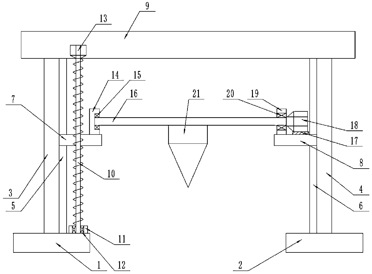
[0020] Such as figure 1 As shown, the present specific embodiment adopts the following technical solutions: a soil drilling machine for use in agriculture, comprising a left base plate 1, a right base plate 2, a left vertical pole 3, a right vertical pole 4, a left slide rail 5, a right slide rail 6, Left slider 7, right slider 8, beam 9, lead screw 10, first bearing housing 11, first bearing 12, first motor 13, second bearing housing 14, second bearing 15, rotating shaft 16, motor base 17. The second motor 18, the third bearing seat 19, the third bearing 20 and the earth drilling machine 21; the middle end of the upper surface of the left bottom plate 1 is fixedly connected with a left vertical rod 3, and the right side of the left vertical rod 3 A left slide rail 5 is fixedly connected to the top, and a left slider 7 is slidably connected to the left slide rail 5; a first bearing seat 11 is fixedly connected to the right side of the upper surface of the left bottom plate 1; ...

Embodiment 2

[0025] Such as figure 1 As shown, the present specific embodiment adopts the following technical solutions: a soil drilling machine for use in agriculture, comprising a left base plate 1, a right base plate 2, a left vertical pole 3, a right vertical pole 4, a left slide rail 5, a right slide rail 6, Left slider 7, right slider 8, beam 9, lead screw 10, first bearing housing 11, first bearing 12, first motor 13, second bearing housing 14, second bearing 15, rotating shaft 16, motor base 17. The second motor 18, the third bearing seat 19, the third bearing 20 and the earth drilling machine 21; the middle end of the upper surface of the left bottom plate 1 is fixedly connected with a left vertical rod 3, and the right side of the left vertical rod 3 A left slide rail 5 is fixedly connected to the top, and a left slider 7 is slidably connected to the left slide rail 5; a first bearing seat 11 is fixedly connected to the right side of the upper surface of the left bottom plate 1; ...


PUM


Abstract

The invention discloses an agricultural soil drilling machine. The agricultural soil drilling machine comprises a left bottom plate, a right bottom plate, a left vertical rod, a right vertical rod, aleft sliding rail, a right sliding rail, a left sliding block, a right sliding block, a cross beam, a lead screw, a first bearing pedestal, a first bearing, a first motor, a second bearing pedestal, asecond bearing, a rotating shaft, a motor base, a second motor, a third bearing pedestal, a third bearing, a soil drilling machine and the like. The structure is reasonable and simple, the productioncost is low, the installation is convenient, the carrying is convenient, the labor is not required to be consumed in the driving and pulling process, and the sampling efficiency is high; the two specifications of soil drilling machines are arranged, and the soil drilling machines of different specifications can be conveniently selected for different types of soil; the two bottom plates are provided with taper rods which can be inserted into the ground, so that the whole equipment can be prevented from toppling over.

Description

Technical field: [0001] The invention relates to the field of agricultural technology, in particular to an agricultural earth drilling machine. Background technique: [0002] The soil sampling device is used to collect soil samples below the surface of the ground. Most of the existing soil sampling devices use manual beating to drive the sampling tube into the soil layer. A large amount of labor is required, and the sampling efficiency is relatively low. However, some hydraulically driven earth drilling devices currently on the market are large in size and extremely inconvenient to carry. They can no longer meet the existing needs, so a technology is needed to make up for this deficiency. Invention content: [0003] The object of the present invention is to provide an agricultural earth-boring machine in order to solve the above problems. [0004] In order to solve the above problems, the present invention provides a technical solution: an agricultural soil drilling machi...

Claims


Application Information

Patent Timeline
Patent Type & Authority Applications(China)
IPC IPC(8): G01N1/08
CPCG01N1/08
Inventor 任新界
Owner 泉州市元本物业管理有限公司
Why Eureka
Try Eureka