
Bulb with clamping-connection structure and special non-contact dismounting and mounting tool of bulb

A light bulb and tool technology, which is applied in the field of non-contact disassembly and assembly tools, can solve the problems of low disassembly and assembly efficiency, inconvenient operation, hidden dangers of high-altitude operation, etc., and achieves the effect of safe and convenient replacement, avoiding damage, and preventing electric shock.

Pending Publication Date: 2018-04-20
徐勇
View PDF0 Cites 0 Cited by
  • Summary
  • Abstract
  • Description
  • Claims
  • Application Information

AI Technical Summary

Problems solved by technology

[0003] The traditional light bulbs are not equipped with a structure for easy disassembly and assembly and are equipped with special disassembly tools. When replacing, the operator directly holds the light bulb with his hand to operate
[0004] However, in practice, it is difficult for people to confirm whether the switch is off after the bulb is damaged. When replacing the bulb by hand, the hand is easy to touch the metal part of the bulb and cause an electric shock, which poses a great safety hazard.
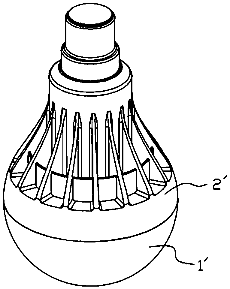
[0005] In addition, if figure 1 As shown in the light bulb, when people replace it, the main force-bearing part is the lower lamp housing 1', and it is easy to loosen it from the lamp holder 2' during replacement and cause the bulb to be damaged
[0006] In addition, the above-mentioned contact-type bulb replacement requires the operator to be able to touch the bulb and operate in a close environment. However, in practice, due to the limitation of the building structure, there is no standard height and distance for the installation position of the bulb. Especially for some factory lighting or street lighting, where the bulbs are installed at least several meters high, they must be operated with the help of ladders and other equipment when changing, which is not only inconvenient to operate, but also high in maintenance costs. There is a great security risk

Method used


Image

  • Bulb with clamping-connection structure and special non-contact dismounting and mounting tool of bulb
  • Bulb with clamping-connection structure and special non-contact dismounting and mounting tool of bulb
  • Bulb with clamping-connection structure and special non-contact dismounting and mounting tool of bulb

Examples


Embodiment approach

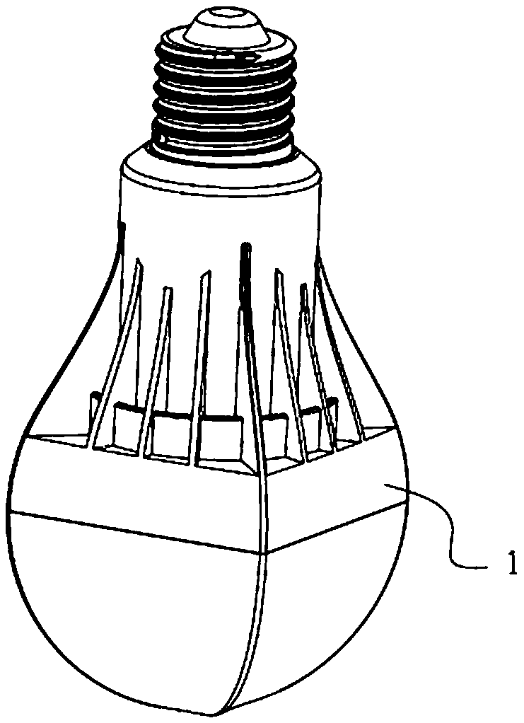
[0035] Such as Figure 5 As shown, it is a second embodiment of a light bulb with a snap-fit ​​structure, which includes a light bulb body 1, and the outer contour of the light bulb body 1 is directly elliptical.

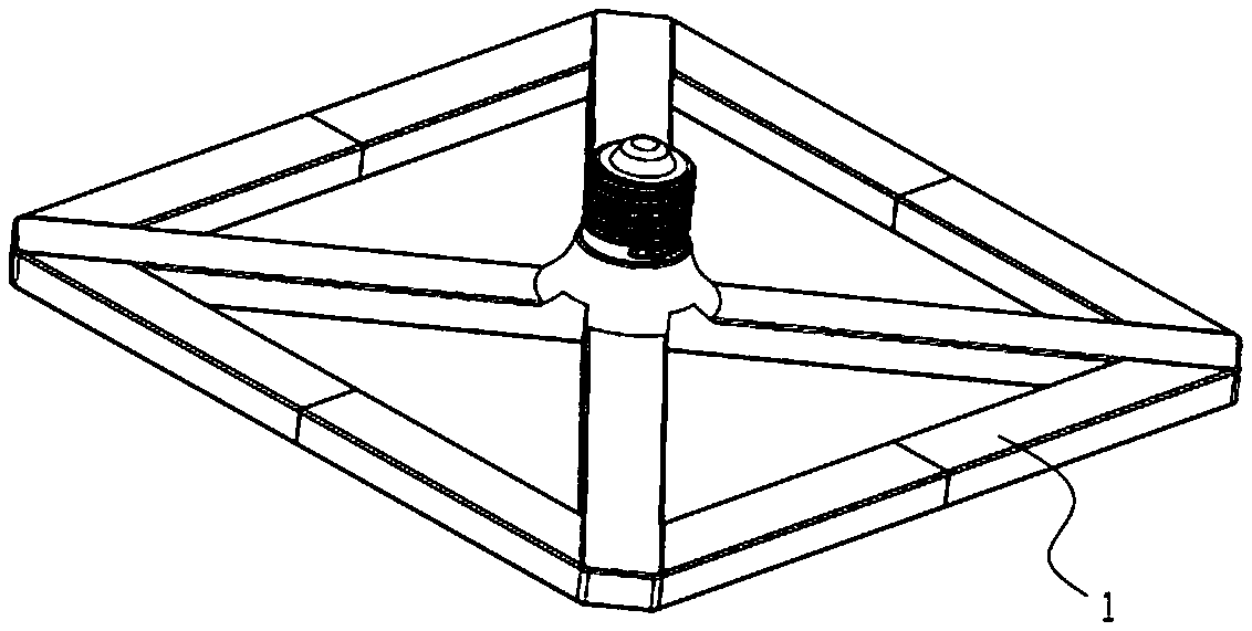
[0036] Such as Figure 6 As shown, it is a third embodiment of a light bulb with a locking structure, which includes a light bulb body 1, and a polygonal locking protrusion 11 is arranged on the light bulb body 1. In practice, the locking protrusion 11 can also be Set into an oval. In this illustration, the engaging protrusion 11 is arranged on the periphery of the bulb body 1. In practice, the engaging protrusion can also be arranged on the top of the bulb body. Its structure is as follows: Figure 7 shown.

[0037] The engaging protrusion 11 is integrally formed with the bulb body 1 or connected separately.

[0038] Such as Figure 8 As shown, it is a special dismounting tool for the light bulb, which includes a connecting sleeve 2, and an engaging groove 21 ...


PUM


Abstract

The invention discloses a bulb with a clamping-connection structure. The bulb comprises a bulb body. The outer contour of the bulb body is arranged in a polygon or oval shape, or the bulb body is provided with a polygonal or oval clamping-connection protrusion. The bulb of the design is provided with the clamping-connection structure facilitating dismounting and mounting, thus, non-contact or remote dismounting and mounting of the bulb can be achieved conveniently in combination with special dismounting and mounting tools during replacement, and the bulb has the characteristics of being safe in dismounting and mounting, simple and practical in structure and low in maintaining cost.

Description

technical field [0001] The invention relates to a light bulb, in particular to a light bulb with an engaging structure and a special non-contact disassembly tool. Background technique [0002] Bulbs are one of the necessary accessories for modern lighting. Regardless of their quality, they always have a certain service life. After they are damaged, they must be replaced manually in order to ensure the brightness of the light. [0003] Traditional light bulbs are not equipped with structures for easy disassembly and assembly and are equipped with special disassembly tools. When replacing, the operator directly holds the light bulb with his hand to operate. [0004] And in reality, after the bulb is damaged, it is difficult for people to confirm whether the switch is off. When the bulb is replaced by hand, the hand is easy to touch the metal part of the bulb and an electric shock occurs, which poses a great potential safety hazard. [0005] In addition, if figure 1 As shown ...

Claims


Application Information

Patent Timeline
IPC IPC(8): F21S2/00F21V17/16
CPCF21S2/00F21V17/164
Inventor 徐勇
Owner 徐勇
Learn More