Free curved surface detection method

A detection method and curved surface technology, which is applied in the direction of measuring devices, testing optical properties, geometric characteristics/aberration measurement, etc., can solve the problems of low processing accuracy, high detection difficulty, high cost, etc., and achieve the effect of improving detection accuracy

Inactive Publication Date: 2018-04-20
全普半导体科技(深圳)有限公司
View PDF5 Cites 14 Cited by
  • Summary
  • Abstract
  • Description
  • Claims
  • Application Information

AI Technical Summary

Problems solved by technology

[0004] However, the detection of the existing optical free-form surface is very difficult, the processing accuracy is not high, and the cost is high. In particular, how

Method used


Image

  • Free curved surface detection method
  • Free curved surface detection method
  • Free curved surface detection method

Examples


Embodiment Construction

[0024] In order to make the content of the present invention clearer and easier to understand, the content of the present invention will be further described below in conjunction with the accompanying drawings. Of course, the present invention is not limited to this specific embodiment, and general replacements known to those skilled in the art are also covered within the protection scope of the present invention.

[0025] The following is attached Figure 1-10 The present invention will be described in further detail with specific examples. It should be noted that the drawings are all in a very simplified form, using imprecise scales, and are only used to facilitate and clearly achieve the purpose of assisting in describing the present embodiment.

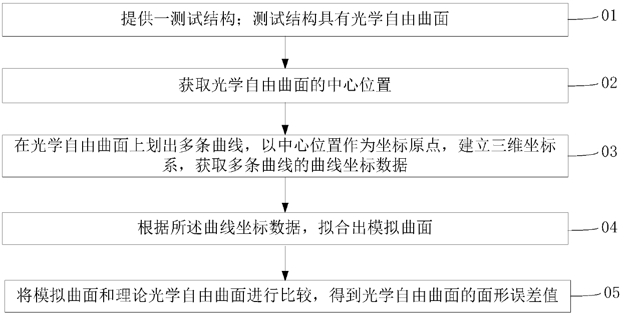
[0026] see figure 1 , a detection method for an optical free-form surface of the present embodiment, comprising:

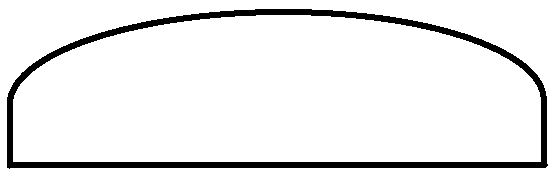
[0027] Step 01: See figure 2 , providing a test structure; the test structure has an optical free-form surface...


PUM


Abstract

The invention provides a free curved surface detection method comprising the following steps: a test structure is provided, the test structure has an optical free curved surface, a central position ofthe optical free curved surface is obtained, a plurality of curved lines are lined out on the optical free curved surface, a three dimensional coordinate system is built while the central position isused as an origin of coordinates, curve coordinate data of the plurality of curved lines is obtained, a simulated curved surface is fitted according to the curve coordinate data, the simulated curvedsurface is compared with a theoretical optical free curved surface, and a surface shape error value of the optical free curved surface is obtained. Via the free curved surface detection method, the optical free curved surface can be effectively measured, and detection precision is improved.

Description

technical field [0001] The invention relates to the technical field of semiconductors, in particular to a detection method for an optical free-form surface. Background technique [0002] Traditional optical systems usually use coaxial systems, such as spherical or aspherical mirrors. However, with the continuous expansion of the application range of optical equipment, the traditional optical system has been unable to meet the requirements of high performance and miniaturization of optical equipment. Therefore, the non-coaxial reflection system came into being. In the non-coaxial optical system, the optical free-form surface has irreplaceable functions such as plane and spherical surface. Therefore, the use of the shape of the optical free-form surface to design according to actual needs makes the application of the optical free-form surface in imaging, lighting, measurement and other fields more and more favored by people. [0003] Optical free-form surfaces usually refer...

Claims


Application Information

Patent Timeline
IPC IPC(8): G01M11/02G01B21/20G01B11/24
CPCG01M11/025G01B11/24G01B21/20
Inventor 汪际军
Owner 全普半导体科技(深圳)有限公司
Why Eureka
Try Eureka