Two-way tensile loading device

A loading device, biaxial stretching technology, applied in measuring devices, using stable tension/pressure testing materials strength, instruments, etc., can solve the problem of high test cost, lack of bidirectional loading test guidance documents, annular device clamping Design difficulties and other problems, to achieve the effect of low test cost

Active Publication Date: 2021-05-07
COMAC +1
View PDF11 Cites 0 Cited by
  • Summary
  • Abstract
  • Description
  • Claims
  • Application Information

AI Technical Summary

Problems solved by technology

However, due to the complexity of bidirectional loading test design, most of the material-level, component-level and even section-level strength tests carried out in the aviation industry are still designed in the form of unidirectional tension. Guidance document for loading tests
[0003] The most common existing two-way loading method is to use two sets of hydraulic loading actuators. This method needs to overcome the steps between the two loading systems, and the test cost is high.
For example, Chinese patent CN200810017989.1 discloses a device that can complete two-way loading on the platform of a unidirectional tensile testing machine, but the device uses welding to fix threaded rods in many places, making the structural installation relatively complicated, and the test can be carried out Part size is too small
Chinese patent CN201310652430.7 discloses a ring-shaped load resolver, the implementation method is relatively simple, but the manufacture of the ring-shaped device and its fixed support design on the test bench will be more difficult
Chinese patent CN201010240086.7 discloses a mechanical bidirectional tensile tester, which can convert out-of-plane uniaxial tensile loads into in-plane biaxial tensile loads of various proportions, but it has more components and a more complex structure. more complex and can only be applied to smaller cross-shaped test pieces

Method used


Image

  • Two-way tensile loading device
  • Two-way tensile loading device
  • Two-way tensile loading device

Examples


Embodiment Construction

[0023] In the following detailed description of the preferred embodiment, reference is made to the accompanying drawings which form a part hereof. The accompanying drawings show, by way of example, specific embodiments in which the invention can be practiced. The illustrated embodiments are not intended to be exhaustive of all embodiments in accordance with the invention. It is to be understood that other embodiments may be utilized and structural or logical changes may be made without departing from the scope of the present invention.

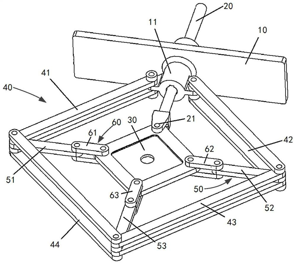
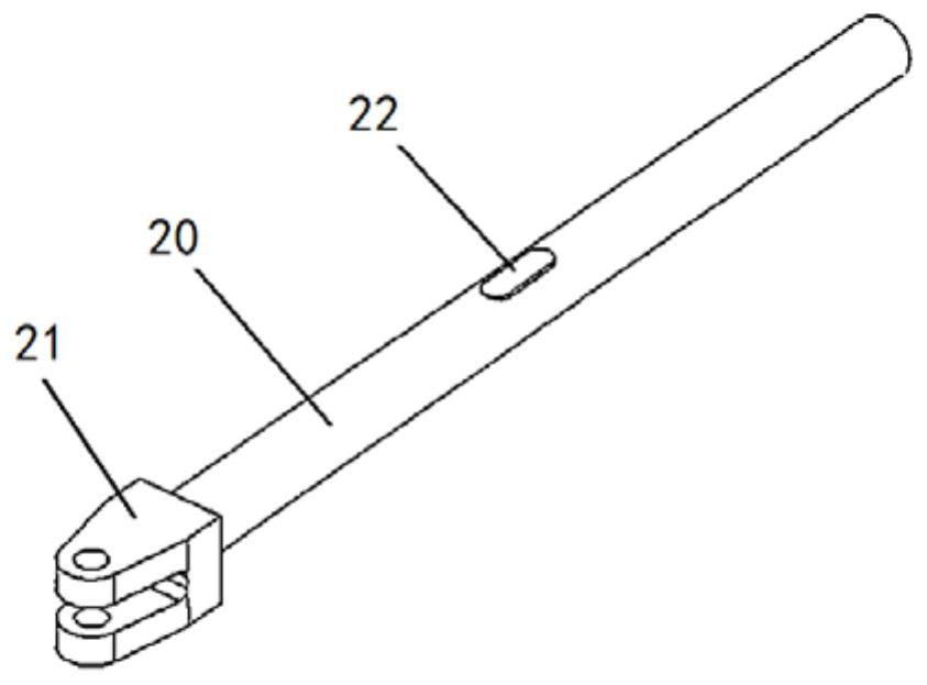
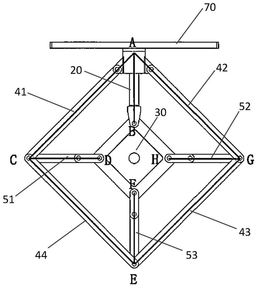
[0024] Such as Figure 1 to Figure 2 shown in . The bidirectional tension loading device according to the present invention includes a fixed base 10, a loading rod 20 and a link mechanism. The loading rod 20 vertically passes through the fixed base 10 and can move vertically relative to the fixed base 10 . The upper end of the loading rod 20 is connected to the mechanical testing machine, and the lower end is provided with an ear piece 21 f...


PUM


Abstract

The invention provides a two-way tensile loading device, comprising: a fixed base; a loading rod, which vertically passes through the fixed base and can move vertically relative to the fixed base, the upper end of the loading rod is connected to a mechanical testing machine, and the lower end There are lugs for pivotally connecting the test piece; and a link mechanism, which converts the load applied by the mechanical testing machine to the test piece through the loading rod into vertical and horizontal tensile loads; wherein the connecting The rod mechanism includes an outer rod assembly and an inner rod assembly. The bidirectional tensile loading device according to the present invention distributes the load by means of the movement of the "umbrella" linkage mechanism, and then transmits the distributed orthogonal bidirectional load to the test piece.

Description

technical field [0001] The invention belongs to the technical field of aeronautical structures and material loading tests, and in particular relates to a bidirectional tensile loading device for bidirectional loading tests, which is suitable for loading tests of square, cross or circular test pieces. Background technique [0002] Most of the structural parts in the aircraft are subjected to two-way stress, and the orthogonal two-way loading test can best simulate the real stress state of aircraft parts. However, due to the complexity of bidirectional loading test design, most of the material-level, component-level and even section-level strength tests carried out in the aviation industry are still designed in the form of unidirectional tension. Load the instruction file for the experiment. [0003] The most common existing two-way loading method is to use two sets of hydraulic loading actuators. This method needs to overcome the steps between the two sets of loading systems...

Claims


Application Information

Patent Timeline
Patent Type & Authority Patents(China)
IPC IPC(8): G01N3/02G01N3/10
CPCG01N3/02G01N3/10
Inventor 王艾伦杨刚黄甫王长江张亦波茅佳兵
Owner COMAC
Why Eureka
Try Eureka