
Power generating device on intelligent identification chip

A technology of generating device and intelligent identification, applied in the direction of adjusting electrical variables, control/regulating systems, instruments, etc., can solve the problem that the power supply voltage value cannot be obtained, the working stability is easily affected by the process, and the PM1 tube is not open for a long time, etc. question

Inactive Publication Date: 2018-04-20
GIANTEC SEMICON LTD
View PDF5 Cites 0 Cited by
  • Summary
  • Abstract
  • Description
  • Claims
  • Application Information

AI Technical Summary

Problems solved by technology

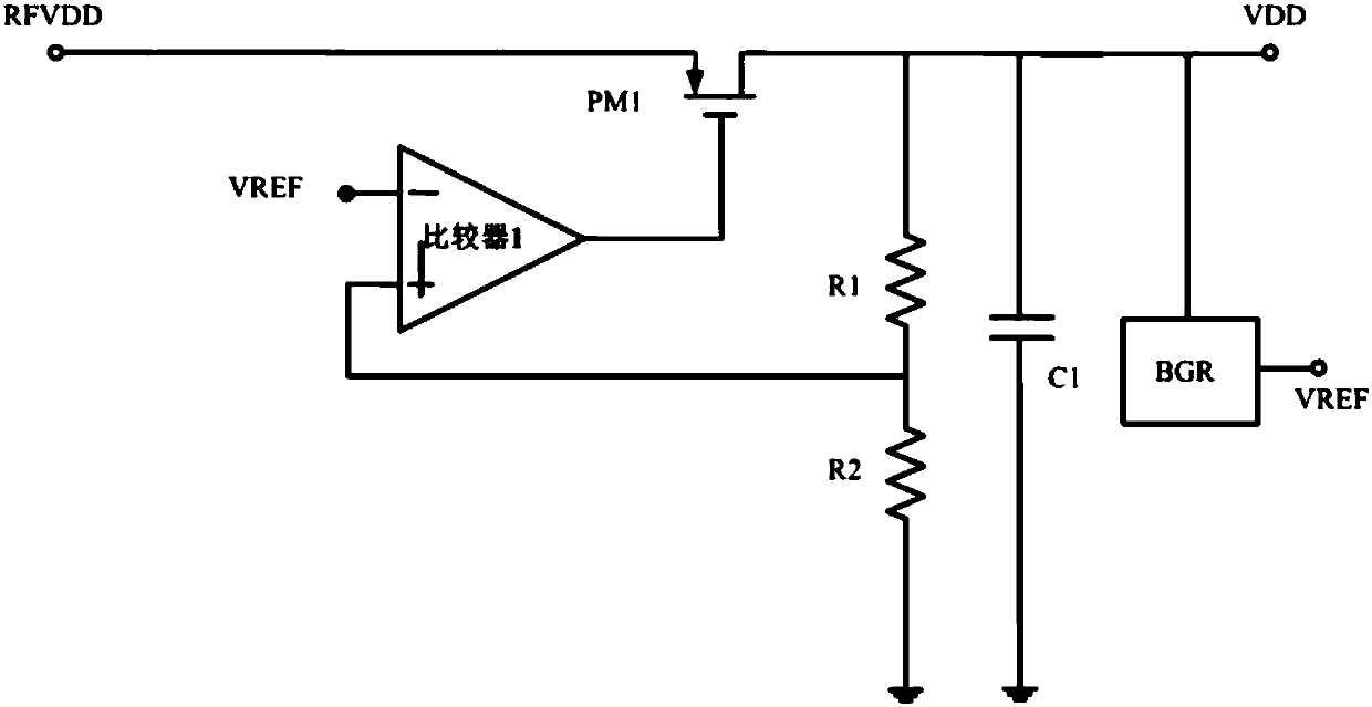
Its potential defect is that the opening time of the PM1 tube is not long enough, so that the BGR has not had time to generate a stable VREF voltage, resulting in the inability to generate the desired power supply voltage value. In addition, the VREF value of the two input terminals of the comparator and the resistor divider value There will be certain fluctuations, causing the output of the comparator to turn off the PMOS when the voltage is not stable, which also leads to the inability to obtain a stable power supply voltage value
In short, the traditional power supply architecture cannot fully guarantee that its functions are correct during the power-on process, and its working stability is relatively easy to be affected by the process.

Method used


Image

  • Power generating device on intelligent identification chip
  • Power generating device on intelligent identification chip
  • Power generating device on intelligent identification chip

Examples


Embodiment Construction

[0038] The present invention will be further elaborated below by describing a preferred specific embodiment in detail in conjunction with the accompanying drawings.

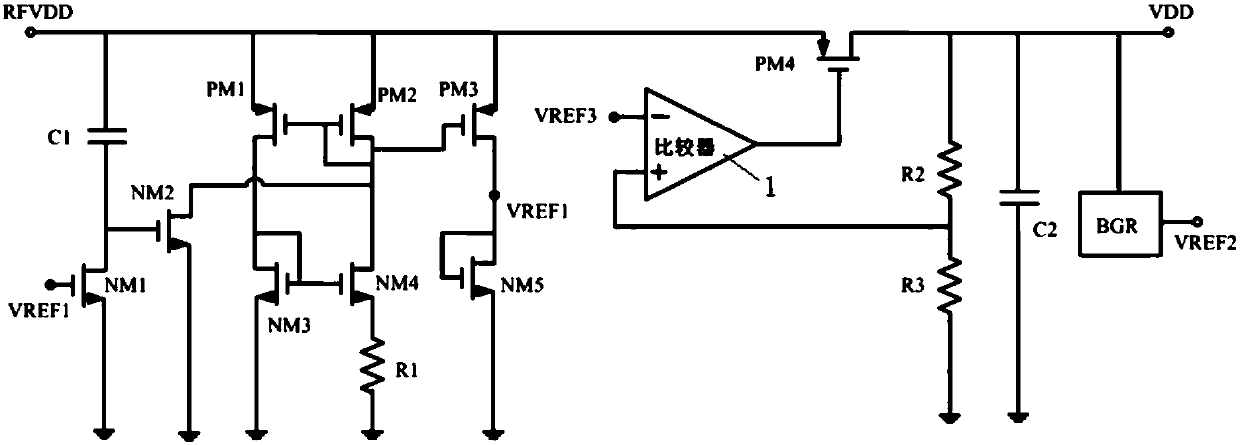
[0039] Such as figure 2 As shown, a power generation device on an intelligent identification chip includes: a bias circuit module, which is powered by a voltage RFVDD and generates a reference voltage VREF1; an LDO module, whose input terminal is connected to the bias circuit module, for The voltage RFVDD is converted to the voltage VDD; the BGR module is connected to the LDO module, and is powered by the voltage VDD and generates a reference voltage VREF2; the voltage comparison module is used to compare the reference voltage VREF1 and the voltage VREF2, and output the corresponding high and low levels; The voltage switching module is used to select the corresponding reference voltage to output according to the corresponding high and low levels of the output, and send the corresponding reference voltage to the ...


PUM


Abstract

The invention discloses a power generating device on an intelligent identification chip. The power generating device comprises a bias circuit module, an LDO module, a BGR module, a voltage comparisonmodule and a voltage switching module, wherein voltage RFVDD supplies power for the bias circuit module, and the bias circuit module generates reference voltage VREF1; the input end of the LDO moduleis connected to the bias circuit module and used for converting the voltage RFVDD into voltage VDD; the BGR module is connected to the LDO module, the voltage VDD supplies power for the BGR module, and the BGR module generates reference voltage VREF2; the voltage comparison module is used for comparing the reference voltage VREF1 and the reference voltage VREF2 and outputting corresponding high and low level; the voltage switching module is used for selectively outputting corresponding reference voltage according to the corresponding output high and low level and transmitting the correspondingoutput reference voltage into the LDO module. By the power generating device, stable and precise power voltage can be generated under various working conditions, and stable working power can be provided for the chip and other modules.

Description

technical field [0001] The invention belongs to the technical field of power supply circuits in analog integrated circuits, and in particular relates to a power generation device on an intelligent identification chip. Background technique [0002] In the traditional power architecture, power-on failure may occur due to improper power architecture setting, so that the correct power voltage value cannot be generated. Such as figure 1 As shown, after RFVDD is powered on, the power supply voltage VDD is boosted up, so that the BGR works to generate VREF, and then the precise VDD voltage is generated through VREF. Its potential defect is that the opening time of the PM1 tube is not long enough, so that the BGR has not had time to generate a stable VREF voltage, resulting in the inability to generate the desired power supply voltage value. In addition, the VREF value of the two input terminals of the comparator and the resistor divider value There will be certain fluctuations, c...

Claims


Application Information

Patent Timeline
Patent Type & Authority Applications(China)
IPC IPC(8): G05F1/56
CPCG05F1/561
Inventor 马和良夏天张红张恒李娟
Owner GIANTEC SEMICON LTD
Learn More