Cooling mechanism for improving maintenance efficiency

A technology of heat dissipation mechanism and maintenance efficiency, applied in the directions of instruments, electrical digital data processing, digital data processing components, etc., can solve the problems of increased thermal resistance, inconvenient maintenance by maintenance personnel, and small contact area between the heat sink and the base, etc. The effect of size, improving heat dissipation capacity, and improving maintenance efficiency

Inactive Publication Date: 2018-04-20
成都西河散热器厂
View PDF0 Cites 0 Cited by
  • Summary
  • Abstract
  • Description
  • Claims
  • Application Information

AI Technical Summary

Problems solved by technology

[0003] At present, most heat sinks are composed of a base and a number of heat dissipation fins. The heat sink fins are usually directly welded on the base. This method makes the contact area between the heat sink and the base smaller and increases the thermal resistance. , which is not conducive to better heat dissipation of electronic products. The heat dissipation fins are welded, so that when some heat dissipation fins are lost, it is not convenient for maintenance personnel to repair them

Method used


Image

  • Cooling mechanism for improving maintenance efficiency
  • Cooling mechanism for improving maintenance efficiency
  • Cooling mechanism for improving maintenance efficiency

Examples


Embodiment

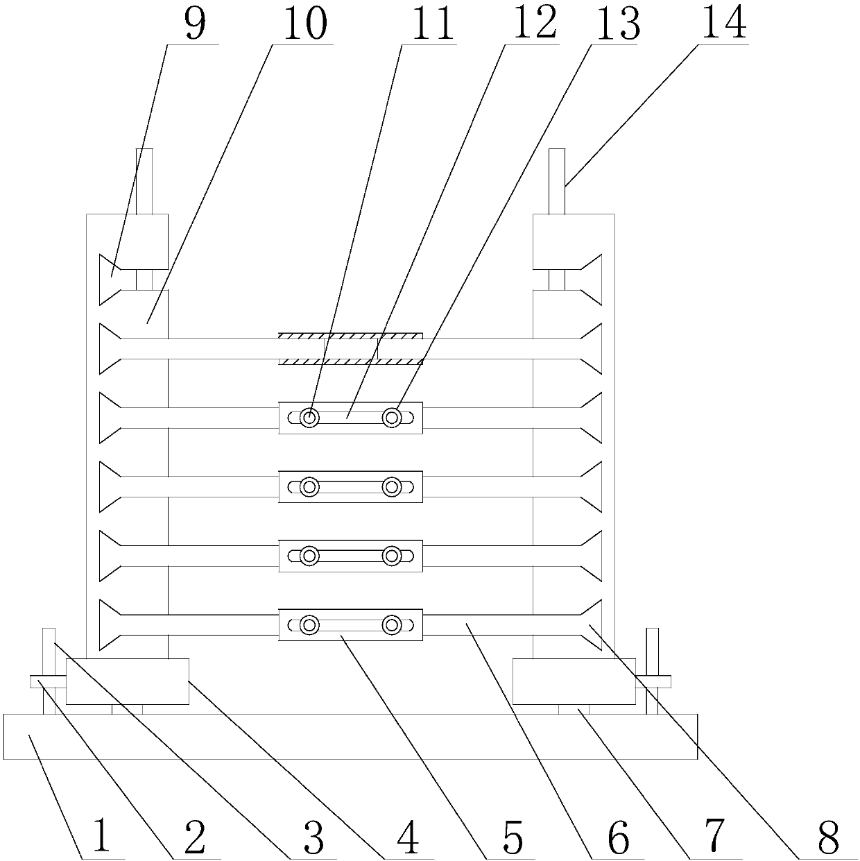
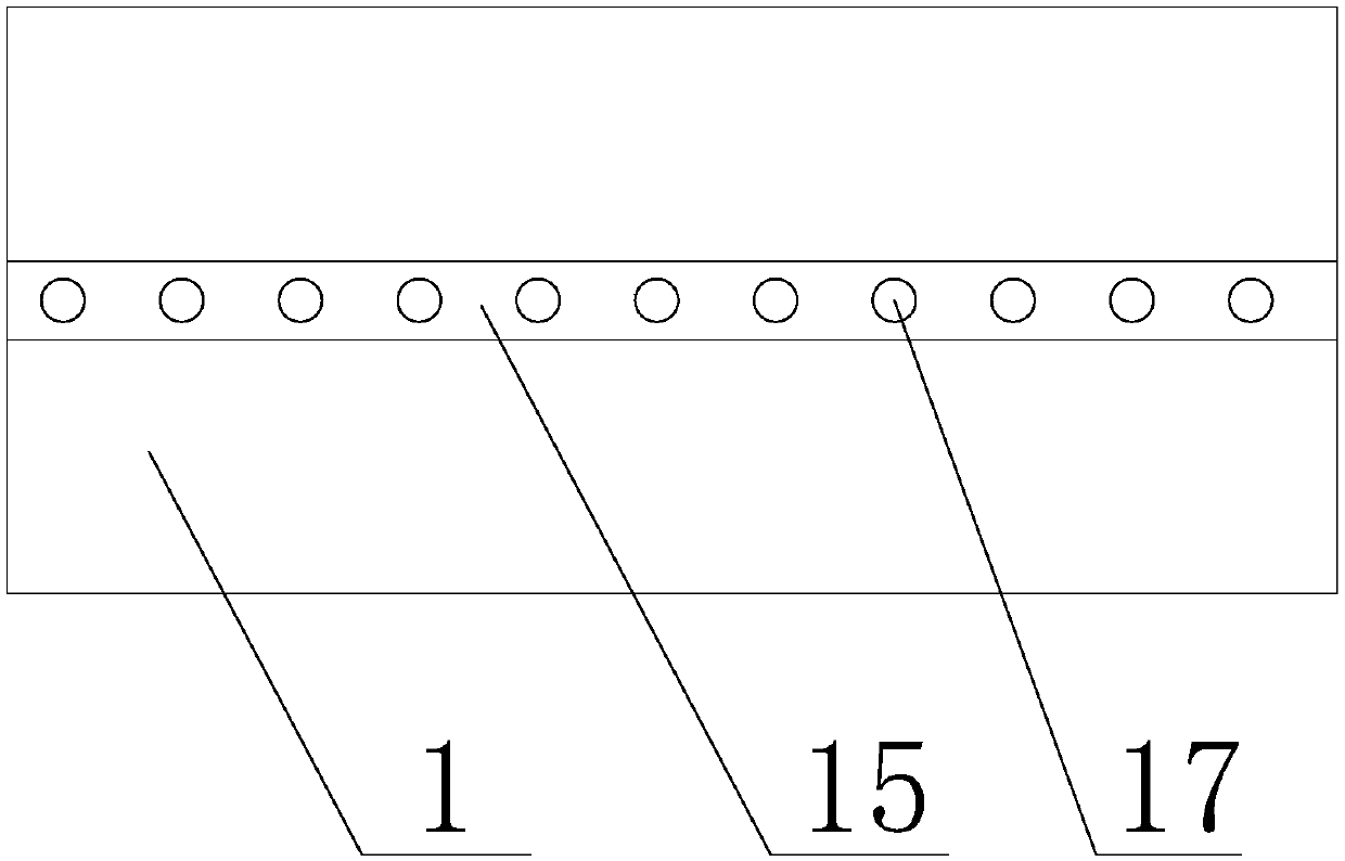
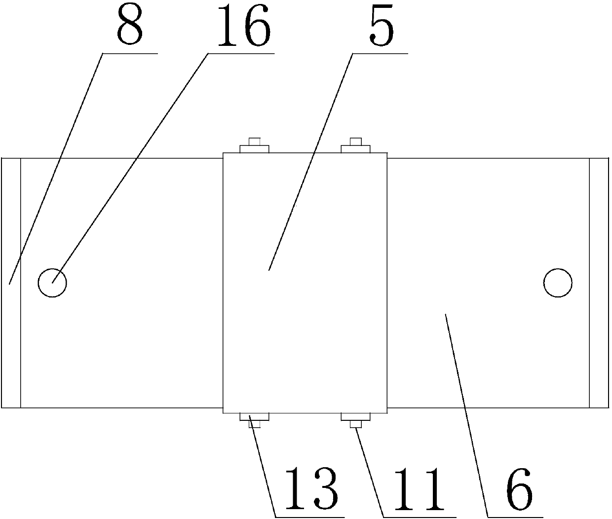
[0022] Such as Figure 1 to Figure 3 As shown, the cooling mechanism for improving the maintenance efficiency of the present invention includes a bottom plate 1 and a plurality of cooling fins 6, the top of the bottom 1 is provided with a chute 15, and two movable blocks 7 are arranged in the chute 15, and the movable block 7 and the The chute 15 is matched, the movable block 7 can move in the chute 15, and some blind holes 17 are evenly arranged in the chute 15, and the top of the movable block 7 is provided with a connecting block 4, and the connecting block 4 can move along with it. The block 7 moves together, and the outside of the connecting block 4 is also provided with a boss 2, and the boss 2 is provided with a positioning rod 3 matched with the blind hole 17, and the positioning rod 3 is vertically inserted on the boss 2 through threads, and rotates Positioning rod 3, positioning rod 3 can move in the blind hole 17 on the same vertical plane with positioning rod 3, an...


PUM


Abstract

The invention discloses a heat dissipation mechanism for improving maintenance efficiency, which includes a base plate and a plurality of heat dissipation fins. The top of the base plate is provided with two side plates, the side plates are respectively located on both sides of the axis of the base, and the side plates can be placed on the base along the horizontal There are several grooves on the side plates, and there are sliders matching the grooves in the grooves. The sliders can move in the grooves. There are also several connecting plates between the two side plates, and cooling fins One end of the piece is connected to the slider, and the other end is inserted into the connecting plate. There is also a chute on the top of the bottom plate. There are several blind holes and two movable blocks matching the chute in the chute. The movable block can move in the chute To move, the top of the movable block is provided with a connecting block, and the outer side of the connecting block is also provided with a boss, and a positioning rod is also provided on the boss, and the positioning rod is vertically inserted on the boss through a thread, and the inside of the chute is evenly A plurality of blind holes matching the positioning rods are provided, and the positioning rods can be connected with the blind holes through threads.

Description

technical field [0001] The invention relates to a radiator, in particular to a heat dissipation mechanism for improving maintenance efficiency. Background technique [0002] Integrated circuits are heavily used in computer components. As we all know, high temperature is the enemy of integrated circuits. High temperature will not only lead to unstable operation of the system, shorten the service life, and may even burn some components. The heat that causes high temperature does not come from outside the computer, but from inside the computer, or inside the integrated circuit. The function of the radiator is to absorb the heat and then dissipate it inside or outside the case to ensure that the temperature of the computer components is normal. Most heat sinks absorb heat by contacting the surface of the heat-generating components, and then transfer the heat to a distant place through various methods, such as the air in the chassis, and then the chassis transfers the hot air ...

Claims


Application Information

Patent Timeline
Patent Type & Authority Applications(China)
IPC IPC(8): G06F1/20
CPCG06F1/20
Inventor 朱敏
Owner 成都西河散热器厂
Why Eureka
Try Eureka