
Business operation state monitoring system

A technology for operating status and monitoring systems, which is applied in transmission systems, distribution line transmission systems, electromagnetic wave transmission systems, etc., and can solve problems such as inability to return station-side signals, channel monitoring, and affecting the operation safety of power systems

Pending Publication Date: 2018-04-20
STATE GRID XINJIANG ELECTRIC POWER CO URUMQI ELECTRIC POWER SUPPLY CO +1
View PDF7 Cites 0 Cited by
  • Summary
  • Abstract
  • Description
  • Claims
  • Application Information

AI Technical Summary

Problems solved by technology

[0002] At present, there is no online monitoring system in the communication industry, and it is impossible to monitor important business channels without interrupting business
At present, with the popularization of intelligent substations, the secondary information and monitoring information of each site are attached to the power optical fiber channel. If the attenuation of the optical fiber channel where the business is located is too large or the optical path is interrupted, the signal at the station end will not be transmitted back, which will affect the power supply. Security of system operation

Method used

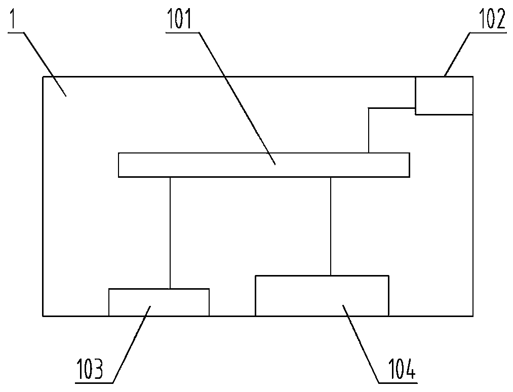
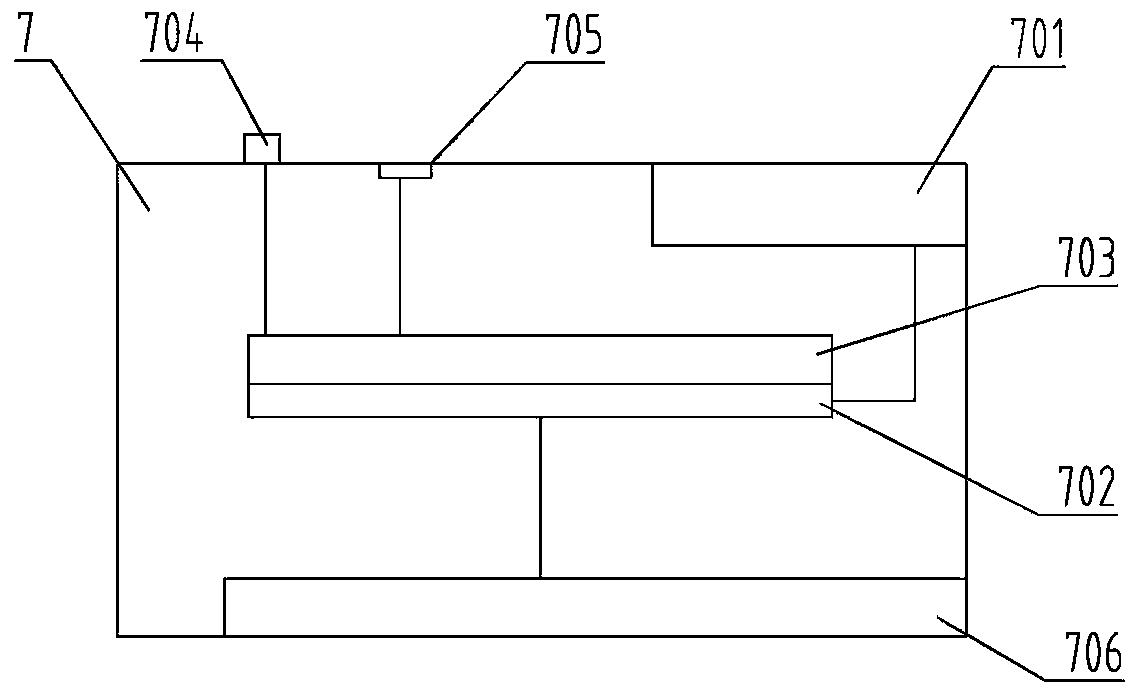

Image

  • Business operation state monitoring system
  • Business operation state monitoring system
  • Business operation state monitoring system

Examples


Embodiment Construction

[0015] The present application is not limited by the following examples, and specific implementation manners can be determined according to the technical solutions of the present application and actual conditions.

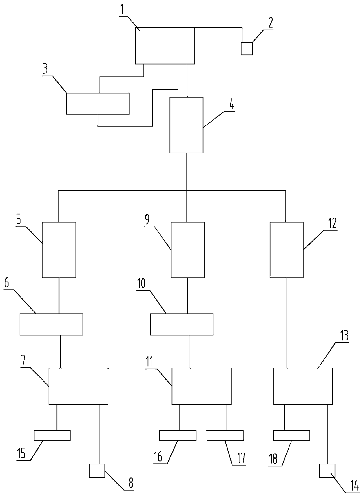
[0016] Such as figure 1 As shown, the service operation status monitoring system includes monitoring and aggregation equipment 1, network management terminal 2, digital distribution frame of aggregation station 3, optical transmission equipment of aggregation station 4, optical transmission equipment of station A, digital distribution frame of station A 6, station A Monitoring terminal equipment 7, station A channel terminal 8, intermediate station optical transmission equipment 9, intermediate station digital distribution frame 10, intermediate station monitoring terminal equipment 11, B station optical transmission equipment 12, B station monitoring terminal equipment 13, and B channel Terminal 14; the output end of the monitoring aggregation device 1 is connecte...


PUM


Abstract

The invention relates to a business online monitoring system and particularly relates to a communication business operation state monitoring system. The system comprises a monitoring aggregation device, a network management end, an aggregation station digital wire distribution frame, an aggregation station optical transmission device, an A station optical transmission device, an A station digitalwire distribution frame, an A station monitoring terminal device, an A station channel terminal, an intermediate station optical transmission device, an intermediate station digital wire distributionframe, an intermediate station monitoring terminal device, a B station optical transmission device, a B station monitoring terminal device and a B station channel terminal. An output end of the monitoring aggregation device is connected with the network management end through a network cable. Through application of the technical scheme, according to the system, the attenuation change or the interruption condition of an optical fiber line can be monitored only by connecting two ends of a to-be-monitored optical fiber line with the A station channel terminal and the B station channel terminal, the attenuation change or the interruption condition can be reflected by the network management end in real time, a discovered optical path hidden danger can be timely processed, the non-planned interruption times of a channel is reduced, and the reliability is improved.

Description

technical field [0001] The present application relates to an online monitoring system for communication services, in particular to a system for monitoring service running status. Background technique [0002] At present, there is no online monitoring system in the communication industry, which cannot monitor the channels of important services without interrupting services. At present, with the popularization of intelligent substations, the secondary information and monitoring information of each station are attached to the power fiber optic channel. If the attenuation of the fiber optic channel where the business is located is too large or the optical path is interrupted, the signal at the station end will not be transmitted back, which will affect the power supply. The security of system operation. Contents of the invention [0003] The purpose of this application is to propose a service operation status monitoring system that reflects the optical fiber channel in time, ...

Claims


Application Information

Patent Timeline
IPC IPC(8): H04B10/25H04B3/54H04Q1/14
CPCH04B3/54H04B10/25H04Q1/14H04Q1/141H04B10/25891
Inventor 朱雪琴王栋孙伟王天峰乔子芩孙祥飞张晨语刘璐杨祎芃张一晨范子涛刘瑞朱江段绪伟缪刚桑遥张志军解鹏李亚平杨春梅
Owner STATE GRID XINJIANG ELECTRIC POWER CO URUMQI ELECTRIC POWER SUPPLY CO
Learn More