
A method and device for power plant booster fan auxiliary machine fault load reduction rb

A technology for the failure of booster fans and auxiliary machines, applied in the field of electric power, can solve the problems of increasing the risk of safe operation of power plants and power grids, lack of long-term risk estimation, and increasing the number of unplanned shutdowns of units, so as to reduce the number of unplanned shutdowns of units. , The effect of reducing the unplanned outage of the unit and ensuring safe operation

Active Publication Date: 2016-05-04
STATE GRID CORP OF CHINA +2
View PDF4 Cites 0 Cited by
  • Summary
  • Abstract
  • Description
  • Claims
  • Application Information

AI Technical Summary

Problems solved by technology

[0008] It can be seen from the above scheme that the essence of the existing domestic technical scheme is that when the booster fan is shut down due to various reasons, in order to ensure the safety of the main engine and the furnace, the boiler MFT, that is, the main fuel of the unit, is tripped directly to stop the unit.
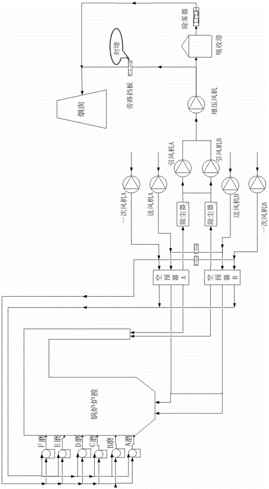
Moreover, the air-smoke system composed of the draft fan and the booster fan after the desulfurization bypass is blocked has not been considered and designed as an integration, thus greatly increasing the number of non-stop of the unit and increasing the safety operation of the power plant and the power grid. risk
[0009] In the process of realizing the present invention, the inventor found that there are at least the following problems in the prior art: since the transformation of the desulfurization bypass flue plugging carried out in 2010 has no fully mature design and implementation case thermal control optimization experience for reference, There is no corresponding technical standard, corresponding work process and normative support, and there is no long-term risk assessment; after the desulfurization transformation, it is necessary to adapt to the new operation mode, and the importance of the desulfurization system has increased sharply, and there is currently no power plant booster fan RB in this field A specific plan to avoid unplanned outage of the unit and ensure the operation of the unit

Method used


Image

  • A method and device for power plant booster fan auxiliary machine fault load reduction rb
  • A method and device for power plant booster fan auxiliary machine fault load reduction rb
  • A method and device for power plant booster fan auxiliary machine fault load reduction rb

Examples


Embodiment Construction

[0033] The following will clearly and completely describe the technical solutions in the embodiments of the present invention with reference to the accompanying drawings in the embodiments of the present invention. Obviously, the described embodiments are only some, not all, embodiments of the present invention. Based on the embodiments of the present invention, all other embodiments obtained by persons of ordinary skill in the art without making creative efforts belong to the protection scope of the present invention.

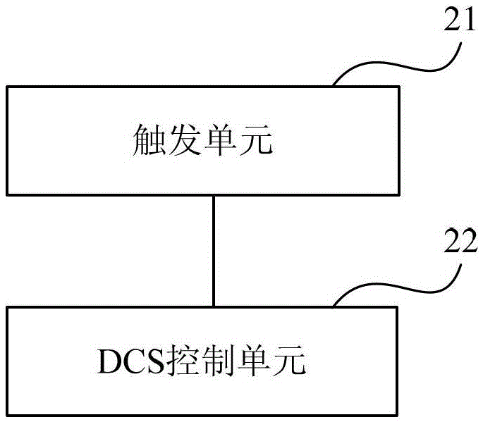
[0034] Embodiments of the present invention provide a method and device for load shedding RB of a booster fan auxiliary machine in a power plant, so as to avoid unplanned outage of the unit and ensure the operation of the unit.

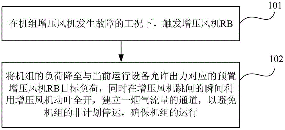
[0035] Such as figure 1 As shown, it is a flow chart of a method for power plant booster fan auxiliary machine failure load reduction RB according to an embodiment of the present invention. The method includes:

[0036] 101. In the w...


PUM


Abstract

A power plant booster fan runback (RB) method, comprising the following steps: when a booster fan of a unit fails, triggering booster fan RB; reducing the load of the unit to a preset booster fan RB target load corresponding to the allowable output of a currently operating device; when the booster fan trips, utilizing the full open state of the movable blades of the booster fan to establish a flue gas flow channel and avoid an unplanned outage of the unit and ensure proper operation. When a booster fan fails, adding a new booster fan RB function avoids the negative effect on the operation of a coal-fired generator unit due to removal of a desulfurization bypass baffle and flue blockage, thus realizing stable operation of the unit. Also disclosed is a power plant booster fan RB device.

Description

technical field [0001] The invention relates to the field of electric power technology, in particular to a method and device for load shedding RB of booster fan auxiliary equipment in a power plant. Background technique [0002] With the refinement of the "Twelfth Five-Year Plan" emission reduction requirements of the Ministry of Environmental Protection, the work of reducing the total amount of pollutants will continue to be promoted. The flue bypass is completely blocked, so the plugging of the desulfurization flue bypass is imperative for each power generation company. At the same time, various documents of the Ministry of Environmental Protection and provincial environmental protection bureaus have repeatedly emphasized the deadline for blocking the desulfurization bypass of coal-fired power plants. Coal-fired power plants, as key emission reduction units, are facing direct pressure. [0003] For the wet desulfurization system with spray tower commonly used in China, th...

Claims


Application Information

Patent Timeline
Patent Type & Authority Patents(China)
IPC IPC(8): F04D27/00
CPCF01K13/02
Inventor 康静秋李卫华解明刘磊张海富顾强肖军政高礼
Owner STATE GRID CORP OF CHINA
Learn More