Puncher convenient to use

A punching machine, a convenient technology, applied in the field of punching machines, can solve problems such as single function, difficult punching, inconvenient mechanical production and processing, etc., and achieve the effect of convenient punching and use

Inactive Publication Date: 2018-04-24
绍兴韵足针纺织有限公司
View PDF0 Cites 13 Cited by
  • Summary
  • Abstract
  • Description
  • Claims
  • Application Information

AI Technical Summary

Problems solved by technology

[0002] The punching machine is composed of four parts that cooperate with each other to complete the punching process. First, the material is moved to the scanning area of ​​the camera of the automatic punching machine. After the camera scans the image, it processes and sends a signal to the control part. After the control part receives the signal, further Process and control the movement of the transmission part, so that the punch moves on the X-axis and Y-axis on the plane. After the movement is completed, the pneumatic part starts to work. The solenoid valve controls the cylinder to perform the punching action, and the automatic punching machine punches the printing positioning hole. The whole action is done in one go, fast, accurate, and efficient; currently, in the field of machinery manufacturing, the punching machine is one of the very common and important processing equipment, and in addition to CNC machine tools, the punching machines used by many small and medium-sized factories have simple structures , the function is single, it is difficult to punch holes on multiple sides of the object, which brings inconvenience to the production and processing of the machine

Method used


Image

  • Puncher convenient to use
  • Puncher convenient to use
  • Puncher convenient to use

Examples


Embodiment Construction

[0027] The following will clearly and completely describe the technical solutions in the embodiments of the present invention with reference to the accompanying drawings in the embodiments of the present invention. Obviously, the described embodiments are only some, not all, embodiments of the present invention. Based on the embodiments of the present invention, all other embodiments obtained by persons of ordinary skill in the art without making creative efforts belong to the protection scope of the present invention.

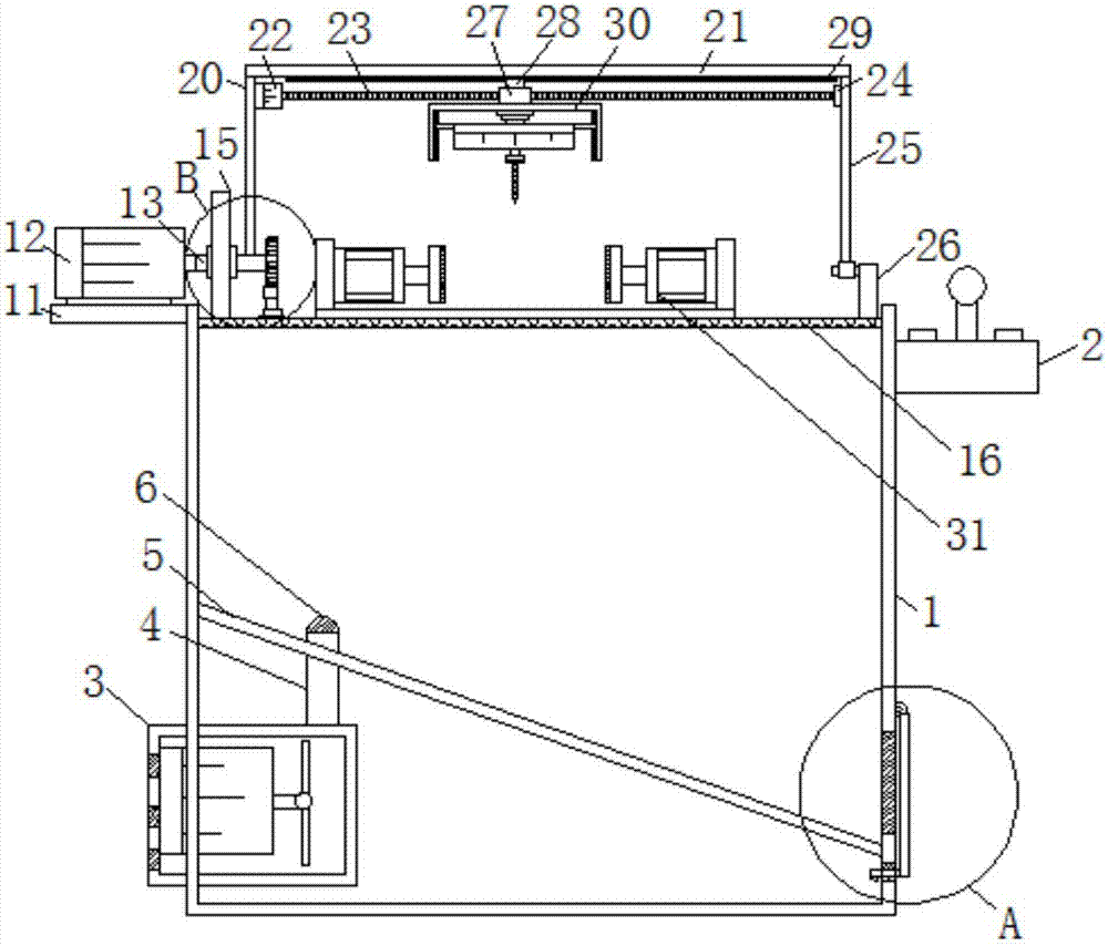
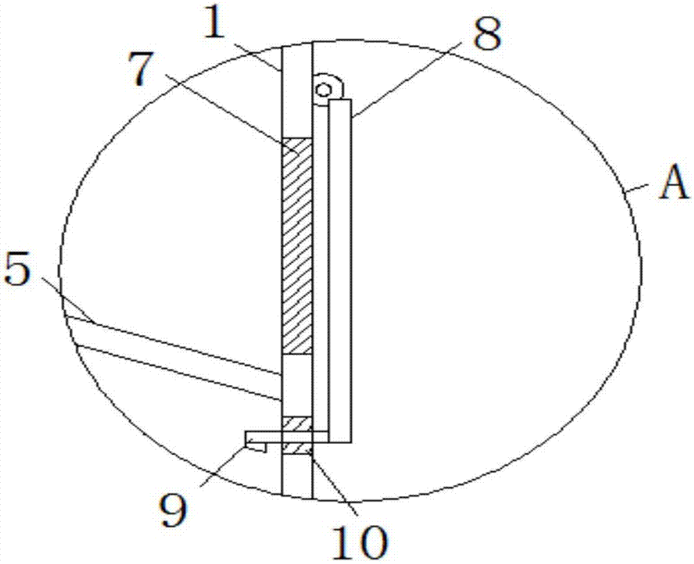
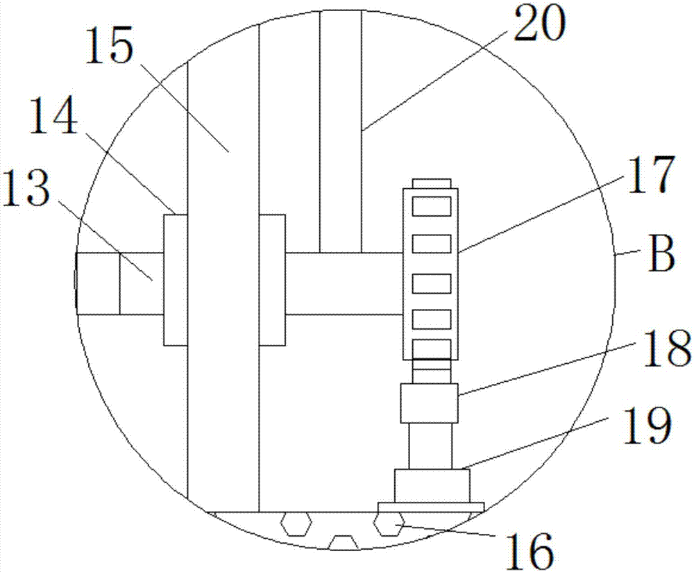
[0028] see Figure 1-6, a convenient punching machine, including a box body 1, one side of the box body 1 is fixedly connected with one side of the controller 2, the other side of the box body 1 is plugged with one side of the fan box 3, and the fan box 3 includes a casing 31 plugged into one side of the box body 1, one side of the inner wall of the casing 31 is fixedly connected to one side of the third motor 32, the output shaft of the third motor 32 is fixe...


PUM


Abstract

The invention relates to the technical field of mechanical equipment, and discloses a convenient punching machine, which includes a box body, one side of the box body is fixedly connected to one side of the controller, and the other side of the box body is connected to the wind turbine. One side of the chassis is plugged in, the top of the fan box is fixedly connected to the bottom of the air duct, the top of the air duct extends through the sloping plate to the outside and is fixedly connected to the bottom of the dust cover, the two sides of the sloping plate They are respectively fixedly connected to both sides of the inner wall of the box, and the side of the box away from the fan box is provided with a discharge port. The easy-to-use punching machine, through the slant plate fixedly connected on the inner wall of the box and the discharge port opened on one side of the box, cooperates with the fan box inserted on one side of the box and the leaking plate fixedly connected on the inner wall of the box, The fan box will generate suction when it is working, so that the drilling debris can be absorbed into the box when drilling. At the same time, the inclined plate and the discharge port facilitate the cleaning of the debris in the box and facilitate the use of drilling.

Description

technical field [0001] The invention relates to the technical field of mechanical equipment, in particular to a convenient punching machine. Background technique [0002] The punching machine is composed of four parts that cooperate with each other to complete the punching process. First, the material is moved to the scanning area of ​​the camera of the automatic punching machine. After the camera scans the image, it processes and sends a signal to the control part. After the control part receives the signal, further Process and control the movement of the transmission part, so that the punch moves on the X-axis and Y-axis on the plane. After the movement is completed, the pneumatic part starts to work. The solenoid valve controls the cylinder to perform the punching action, and the automatic punching machine punches the printing positioning hole. The whole action is done in one go, fast, accurate, and efficient; currently, in the field of machinery manufacturing, the punchi...

Claims


Application Information

Patent Timeline
Patent Type & Authority Applications(China)
IPC IPC(8): B26F1/16B26D7/18B26D7/26B26D7/01
CPCB26F1/16B26D7/01B26D7/1863B26D7/2628
Inventor 孙巧萍俞小红
Owner 绍兴韵足针纺织有限公司
Why Eureka
Try Eureka