
Duct type air conditioner water pan limiting clamping plate and duct type air conditioner

A water-receiving pan and air duct machine technology is applied in the fields of preventing condensate water, space heating and ventilation details, and household heating, etc. It can solve the problems of complex assembly process, inconvenient disassembly and maintenance, easy aging and deformation, and hidden dangers. To achieve the effect of safe and convenient maintenance and easy installation

Active Publication Date: 2018-04-24
HISENSE (SHANDONG) AIR CONDITIONING CO LTD
View PDF14 Cites 2 Cited by
  • Summary
  • Abstract
  • Description
  • Claims
  • Application Information

AI Technical Summary

Problems solved by technology

[0005] At present, most of the structure and fixing methods of the evaporator and the water receiving tray of the existing air duct machine on the market use the metal water receiving tray to be directly fixed to the evaporator or the plastic water receiving tray is assembled by buckling and clamping. The assembly process is complicated, the disassembly and maintenance are inconvenient, or it is easy to age and deform, which has potential safety hazards and other shortcomings

Method used


Image

  • Duct type air conditioner water pan limiting clamping plate and duct type air conditioner
  • Duct type air conditioner water pan limiting clamping plate and duct type air conditioner
  • Duct type air conditioner water pan limiting clamping plate and duct type air conditioner

Examples


Embodiment Construction

[0024] The specific implementation manners of the present invention will be further described in detail below in conjunction with the accompanying drawings.

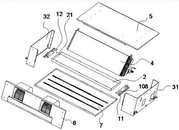
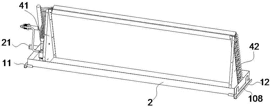
[0025] refer to figure 1 , the air duct machine of the present invention includes a water receiving tray 2, a side plate 3, an evaporator 4, a top plate 5, a fan system 6, a bottom plate 7 and a clamping plate; the fan system 6 is fixedly connected with the top plate 5; the evaporator 4 and the top plate 5 and the side plate 3 are fixedly connected together; the water receiving tray 2 is located under the evaporator 4, and is used to receive and discharge the condensed water on the evaporator 4; and the water receiving tray 2 is fixed on the side plate 3 through a clamping plate ; The bottom plate 7 is fixedly connected with the side plate 3 and the fan system 6, which is convenient for installation. When the air-conditioning maintenance needs to remove the bottom plate 7, the water receiving tray 2 is kept in its insta...


PUM


Abstract

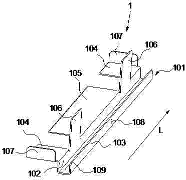
The invention discloses a duct type air conditioner water pan limiting clamping plate. The duct type air conditioner water pan limiting clamping plate comprises a transverse beam. The longitudinal section of the transverse beam is in a U shape and comprises a first groove wall and a second groove wall. First bearing portions and a second bearing portion which extend outwards and are perpendicularto the first groove wall are arranged along the edge of the first groove wall. The first bearing portions are located at the two ends of the transverse beam, the second bearing portion is located in the middle of the transverse beam, and spacer regions are arranged between the first bearing portions and the second bearing portion. The first bearing portions and the second bearing port are used forbearing the bottom of a water pan. Limiting portions extending upward along the first groove wall are arranged in the spacer regions, abut against a left side plate and a right side plate of the water pan, and are used for limiting the water pan in a left-right mode. Vertically upward flanging are arranged along the edges of the ends of the first bearing portions, abut against a front side plateand a rear side plate of the water pan, and are used for limiting the water pan in a front-rear mode. A duct type air conditioner comprises two duct type air conditioner water pan limiting clamping plates which are arranged at the left end and right end of the water pan correspondingly, support the water pan and limit the water pan in left-right and front-rear modes. Mounting is convenient, and dismounting is convenient during maintaining.

Description

technical field [0001] The invention belongs to the technical field of air conditioning, and in particular relates to a limiting clamping plate for a water tray of an air duct machine and an air duct machine. Background technique [0002] The current air-conditioning indoor unit generally includes an indoor unit case, an evaporator installed inside the indoor unit case, and a fan system. Then the air with higher temperature flows through the heat exchanger and exchanges heat with the heat exchanger to form low-temperature air, and the low-temperature air is blown into the room through the air outlet of the box to achieve the purpose of cooling the indoor environment. [0003] When the indoor air with higher temperature encounters the evaporator with lower temperature, when the air with water vapor passes through the evaporator, the water vapor inside is condensed and separated into water droplets. As the water droplets accumulate more and more, they will eventually flow dow...

Claims


Application Information

Patent Timeline
IPC IPC(8): F24F13/22
CPCF24F13/222
Inventor 李典红王世科李召勇焦学超杜建伟梁洪启
Owner HISENSE (SHANDONG) AIR CONDITIONING CO LTD
Learn More