Wheel assembly with motor and vehicle braking device

A technology of wheel components and braking devices, applied in the direction of electric power devices, brake components, electrical devices, etc., can solve the problems of impossible replacement of motors, and achieve the effects of easy maintenance, easy independent inspection, and simple structure

Active Publication Date: 2016-11-09
FRENI BREMBO SPA
View PDF12 Cites 10 Cited by
  • Summary
  • Abstract
  • Description
  • Claims
  • Application Information

AI Technical Summary

Problems solved by technology

[0030] These solutions, while able to solve the serious problem of the motor functioning effectively, do not address the fact that it also makes it worse to have structural simplicity and reduce the possibility of maintenance, in fact making it impossible to replace the entire rim, motor and caliper body assembly. It is not possible to replace the motor without

Method used


Image

  • Wheel assembly with motor and vehicle braking device
  • Wheel assembly with motor and vehicle braking device
  • Wheel assembly with motor and vehicle braking device

Examples


Embodiment Construction

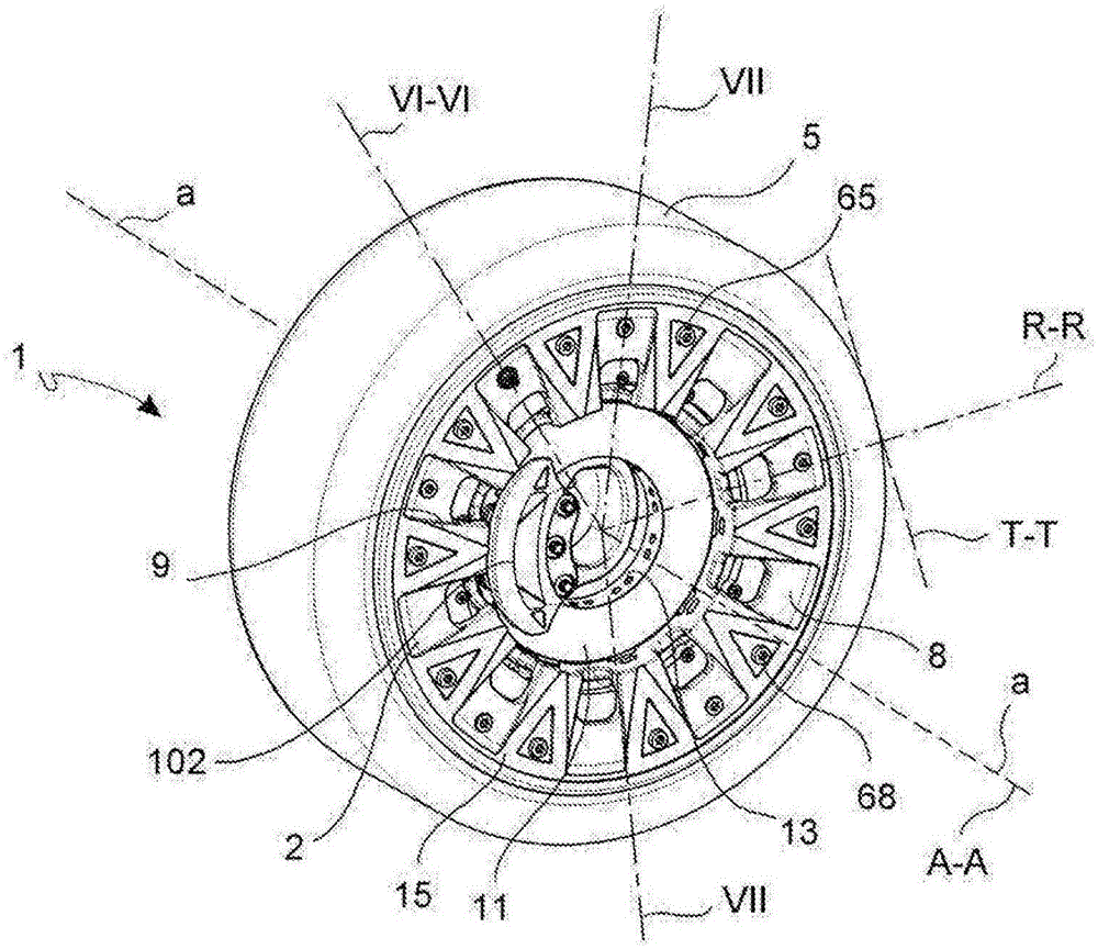
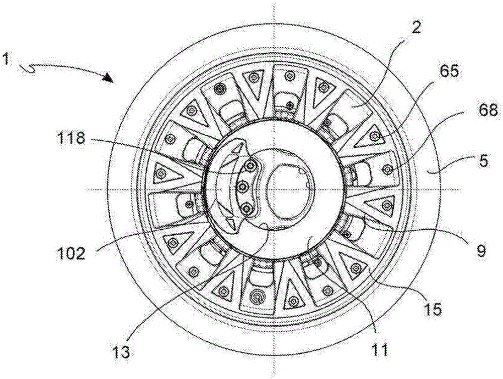
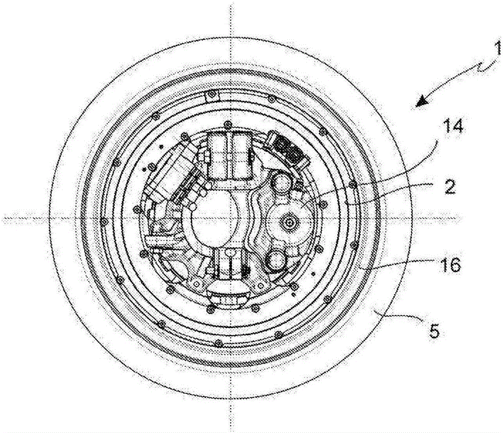
[0082] With reference to the above-mentioned figures and according to a general form of embodiment, a wheel assembly 1 of a vehicle comprises a rim 2 adapted to rotate about an axis of rotation a-a and defines an axial direction A-A parallel to or coincident with said axis of rotation a-a, an orthogonal radial direction R-R and the circumferential direction, the tangential direction T-T orthogonal to the axial direction A-A and the radial direction R-R.

[0083] The rim 2 has a radially outer side, or outer side 3 , facing away from the axis of rotation a-a, and a radially inner side, or inner side 4, facing the axis of rotation a-a. The outside of said rim is adapted to receive a tire 5 and the inside forms a cylindrical rim chamber 54 radially delimited by said inside 4 .

[0084] Furthermore, the wheel assembly includes an electric motor 306 including a rotor 307 and a stator 308 . The rotor 307 is coaxially supported to the stator 308 freely rotatable. The stator is fixe...


PUM


Abstract

A wheel assembly (1) for a vehicle, uncommonly capable of a compact construction and ease of maintenance, comprises: a wheel rim (2) suitable to rotate around an axis of rotation (a- a), defining an axial direction (A-A) parallel or coincident with said axis of rotation (a-a), an orthogonal radial direction (R-R), and a circumferential direction locally coincident with a tangential direction (T-T) orthogonal to the axial direction (A-A) and the radial direction (R-R), said wheel rim (2) having a radially outer side, or outer side (3), opposite the axis of rotation (a-a), and a radially inner side, or inner side (4), facing the axis of rotation (a-a), said rim being suitable to receive externally a tyre (5), and wherein said wheel rim forms internally a cylindrical chamber of the rim (54) delimited radially from said inner side (4); a motor (306) comprising a rotor (307) and a stator (308); said rotor (307) being supported, free to rotate, on said stator (308); said stator being fixed to a stator support (120); said motor (306) being housed in the said cylindrical wheel rim chamber (54) of said wheel rim (2 ); said rotor (307) is selectively, removably and rigidly connected to the inner side (4) of said wheel rim (2), avoiding the interposition of elastic members or damping members; said assembly (1) also comprising a braking device (10), said device comprising a disc brake disc (11) having a radially outer edge (12) and a radially inner edge (13), said braking device (10) further comprising a disc brake caliper (14) selectively, removably and rigidly connected, directly or indirectly, to said stator support (120), said disk brake caliper (14) being placed with its active part (21) astride the inner edge (13) of said disc brake disc (ID; in which said wheel rim (2) is made in two parts (15, 16) selectively and removably connected with each other to form a wheel rim body (17); and wherein one of the two parts of said wheel rim (15) forms in a single piece at least one spoke (18) that protrudes radially towards the axis of rotation (a-a); and wherein said disc (11) is connected with its outer edge (12) to said at least one spoke (18).

Description

technical field [0001] The invention relates to a wheel assembly, including a wheel rim, a motor and a vehicle braking device. [0002] In particular, the present invention relates to a wheel assembly comprising a rim with an electric motor and vehicle brakes inside. Background technique [0003] A wheel including an electric motor inside the wheel (in-wheel motor system) aims at obtaining direct transmission of motion to the rim and realizing an efficient vehicle, as well as reducing the number of moving parts and improving the transmission efficiency of driving force. [0004] Such solutions have been known for a long time, such as the Launer-Porsche car ( Lohner-Prosche). [0005] (see: [0006] http: / / www.porsche.com / international / aboutporsche / responsibility / environment / hybrid / lohner / [0007] and [0008] http: / / www.porsche.com / museum / de / ). [0009] Document WO 2008 / 144517 by MATERIALWERKS LLC shows a wheel arrangement with a propulsion system for alternate...

Claims


Application Information

Patent Timeline
Patent Type & Authority Applications(China)
IPC IPC(8): B60K7/00B60T1/06
CPCB60K7/0007B60T1/065B60K2007/0092B60L2220/44B60B25/004F16D65/12B60K2007/0038F16D2065/1364F16D2065/1384B60K11/02B60K2001/006F16D55/225
Inventor 本亚明·谢夫奇克保罗·萨拉里卡尔多·阿里戈尼克里斯蒂安·克里帕安德烈亚·米莱恩斯亚历山德罗·乔蒂
Owner FRENI BREMBO SPA
Why Eureka
Try Eureka