
Clamp device for circuit de-icing

A clamping device and line-type technology, which is applied to coupling devices, components of connecting devices, circuits, etc., can solve the problems of time-consuming and labor-intensive shorting, poor operation safety, and low ice-melting efficiency, and achieve convenient operation and low cost , Improve the effect of operational safety

Pending Publication Date: 2018-04-24
GUIZHOU POWER GRID CO LTD
View PDF0 Cites 5 Cited by
  • Summary
  • Abstract
  • Description
  • Claims
  • Application Information

AI Technical Summary

Problems solved by technology

[0003] The technical problem to be solved by the present invention is to provide a line-type ice-melting clamping device to solve the problems of poor operational safety, cumbersome operation, time-consuming and labor-intensive short-circuiting and low ice-melting efficiency existing in the prior art

Method used


Image

  • Clamp device for circuit de-icing
  • Clamp device for circuit de-icing
  • Clamp device for circuit de-icing

Examples


Embodiment

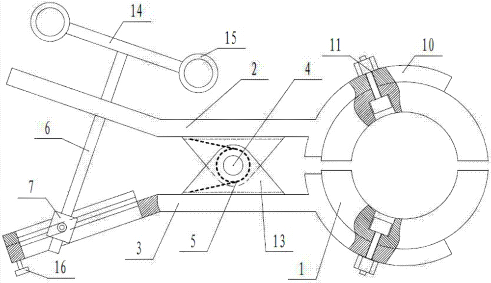
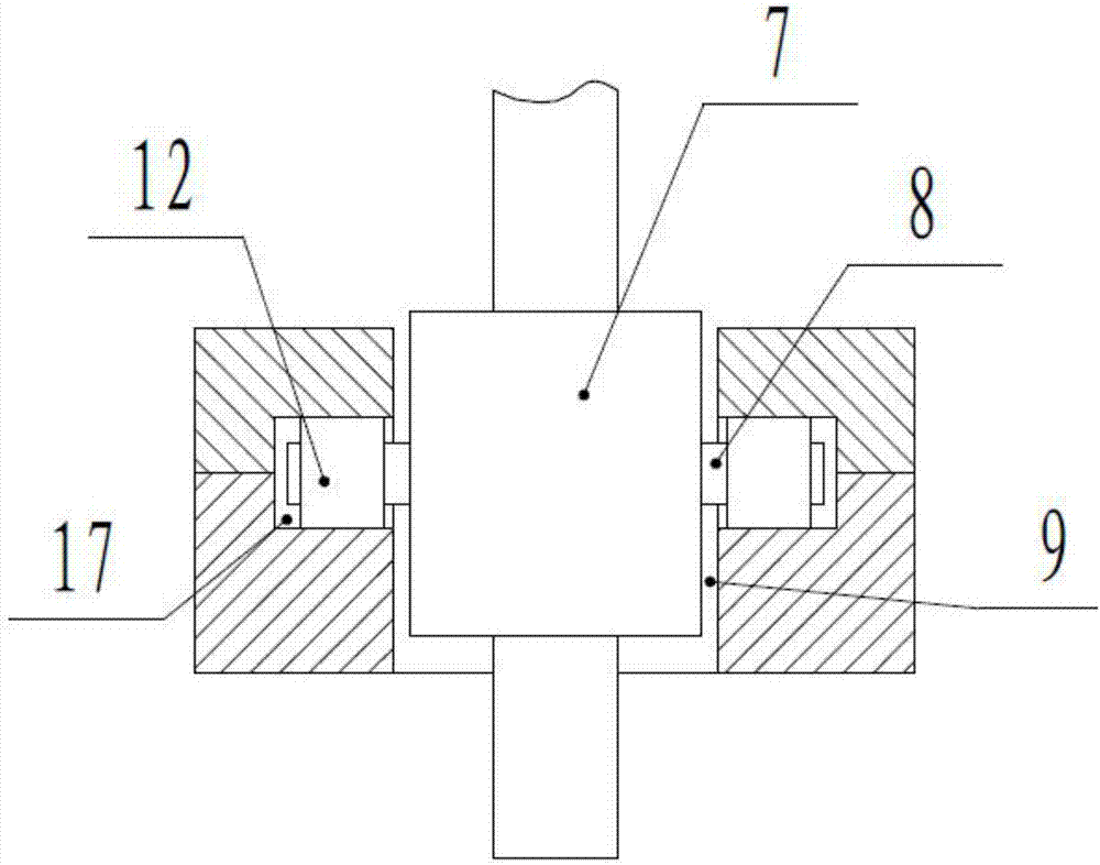
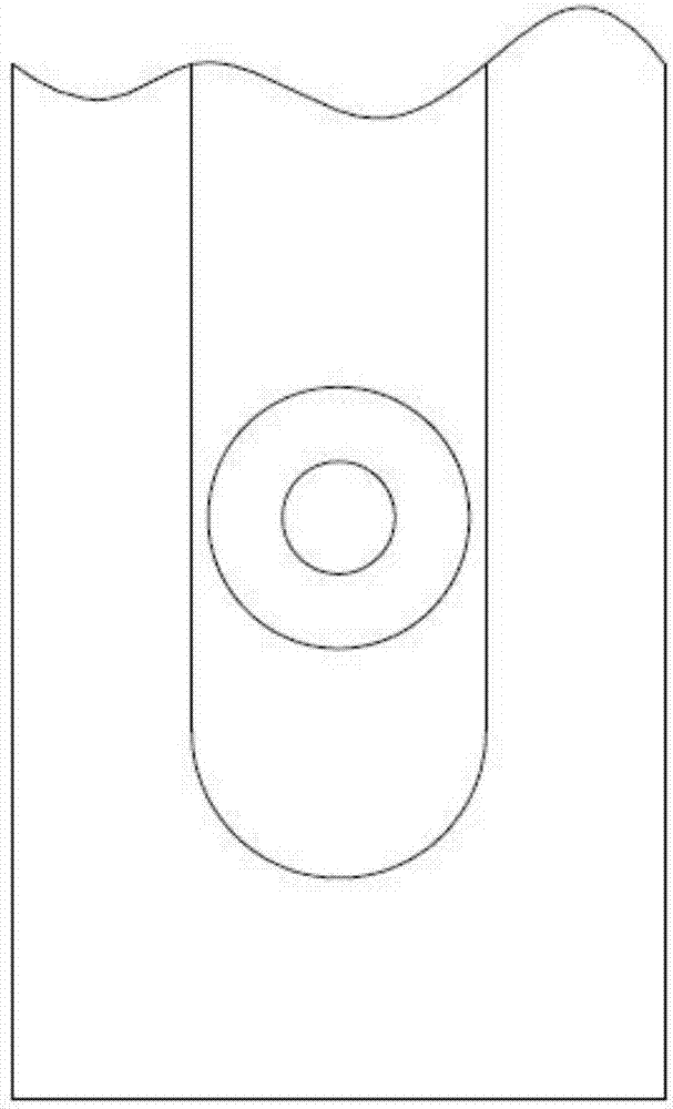
[0018] Example: such as Figure 1-Figure 3 As shown, a line-type ice-melting clamping device includes two conductive arc-shaped clamping pieces 1, and the two arc-shaped clamping pieces 1 are symmetrically installed on the front ends of the clamping plate 1 2 and the clamping plate 2 3 respectively, and the clamping plate The first 2 and the clamping plate 2 3 are connected by the hinge shaft 4, the hinge shaft 4 is provided with a reset spring 5 and the free state of the clamping plate 1 2 and the clamping plate 2 3 is closed, and the tail end of the clamping plate 1 2 is screw connected There is a dismounting screw 6, and the end of the dismounting screw 6 protruding toward the clamping plate 2 3 is connected to a screw nut 7 that can rotate and slide along the length direction of the clamping plate 2 3, and the screw nut 7 is connected to the clamping plate 1 2 The threaded hole connecting the disassembly screw 6 rotates in the opposite direction. This device is used to gui...


PUM


Abstract

The invention discloses a clamp device for circuit de-icing. The clamp device includes two conducting arc-shaped clamping sheets mounted on the front of a clamp board I and the front end of a clamp board II symmetrically. The clamp board I and the clamp board II are connected through an articulated shaft. The articulated shaft is provided with a reset spring and the free state of the clamp board Iand the clamp board II is closing. A tail end of the clamp board I is threaded with a dismounting screw rod. One end of the dismounting screw rod extending towards the clamp board II is connected toa nut capable of rotating and sliding along the length direction of the clamp board II. The rotation direction of the nut is opposite to the thread direction of a thread hole connected with the dismounting screw rod in the clamp board I. According to the invention, the two arc-shaped clamping sheets clamp a lead for de-icing. The mounting is simplified, so that convenience is achieved and time andlabor are saved. A worker does not need to ride on the lead, so that operation safety is improved and the de-icing efficiency is greatly improved. In dismounting, a worker only needs to unscrew and rotate the dismounting screw rod in the reverse direction, so that the device is convenient in mounting and dismounting. By employing the nut and the thread hole in the clamp board having opposite rotation directions, release and clamping adjustment quickness is achieved.

Description

technical field [0001] The invention relates to a line-type ice-melting clamping device, which belongs to the technical field of ice-melting devices. Background technique [0002] At present, when the 35-110kV guiding road is melting the line, most of them usually use the combination of amp clamp and wire to short-circuit the line. During the implementation of this method, tools such as amp gun and hammer are needed. Riding out the wires and installing the amp clamp to short-circuit the three-phase wires, the installation process is cumbersome. On the one hand, it is not conducive to the safety of the operators. On the other hand, the short-circuiting process takes a long time, which is not conducive to the rapid melting of ice on the line. Contents of the invention [0003] The technical problem to be solved by the present invention is to provide a line-type ice-melting clamping device to solve the problems of poor operational safety, cumbersome operation, time-consuming...

Claims


Application Information

Patent Timeline
Patent Type & Authority Applications(China)
IPC IPC(8): H01R4/48H01R13/02H01R13/621H01R31/08H02G7/16
CPCH01R4/48H01R13/02H01R13/6215H01R31/08H02G7/16
Inventor 李生福曾宪武王先锋张黎唐猛谭谋吴雪冬尤明洋徐朝
Owner GUIZHOU POWER GRID CO LTD
Learn More