Tube taking device

A technology of hooking and U-shaped tubes, which is applied in the direction of transportation and packaging, conveyor objects, etc., can solve the problems of low processing efficiency, heat dissipation pipes destroying heat sinks, and a large number of heat sinks, so as to improve assembly efficiency and improve hooking efficiency. Take the effect of efficiency

Inactive Publication Date: 2019-07-19
SHANDONG UNIV
View PDF5 Cites 0 Cited by
  • Summary
  • Abstract
  • Description
  • Claims
  • Application Information

AI Technical Summary

Problems solved by technology

[0003] Due to the large number of fins in the heat exchanger, and each fin is relatively thin, the diameter of the tubes that need to be intubated is small and there are many pipelines. If the intubation process is not well controlled, it is easy for the heat sink to damage the fins.
In the prior art, the assembly of the heat exchanger is done manually, and the tubes are manually taken out one by one, and then inserted into the fins of the heat exchanger one by one. It is uncontrollable and easy to cause damage to the U-shaped tube

Method used


Image

  • Tube taking device
  • Tube taking device
  • Tube taking device

Examples


Embodiment Construction

[0035] The specific implementation manners of the present invention will be clearly and completely described below in conjunction with the accompanying drawings. Apparently, the embodiments described in the specific implementation are only some of the embodiments of the present invention, rather than all the embodiments. Based on the embodiments of the present invention, all other embodiments obtained by persons of ordinary skill in the art without making creative efforts belong to the protection scope of the present invention.

[0036] In the description of the present invention, it should be noted that the orientations or positional relationships indicated by the terms "up", "down", "front", "rear", "clockwise", "counterclockwise" etc. are based on the drawings The positional relationship shown is only for the convenience of describing the present invention and simplifying the description, but does not indicate or imply that the referred device or element must have a specifi...


PUM


Abstract

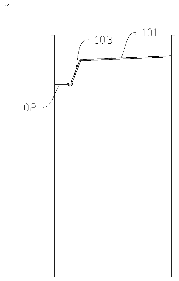
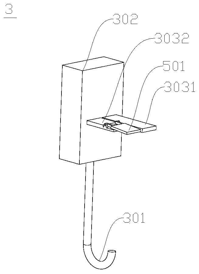
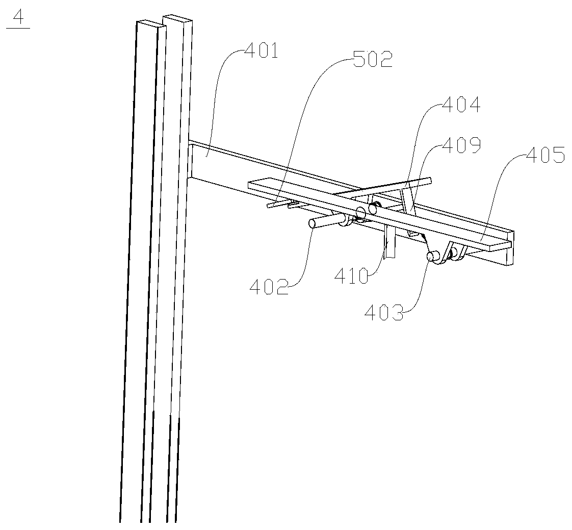
A tube taking device, comprising a U-shaped tube bracket and a movable mechanical hook structure for hooking the U-shaped tube; the U-shaped tube bracket includes a storage part beam for placing batches of U-shaped tubes, and is connected to the storage part beam The hooking part crossbeam for placing the U-shaped pipe to be hooked, the pipe taking device further includes an auxiliary crossbeam, and a release stop structure for stopping and releasing the U-shaped pipe on the storage part crossbeam is installed in parallel on the auxiliary crossbeam, including The release arm and the stop arm are respectively installed on the auxiliary beam through the rotation shaft; the auxiliary beam is further equipped with a stop block, which is located between the two rotation shafts; the release arm and the stop arm are provided with a beam facing the storage part The U-shaped tube stop block stretching out in the direction, the U-shaped tube stop block on the stop arm is close to the U-shaped tube stored on the storage part crossbeam. The invention provides a tube taking device which can automatically hook a U-shaped tube. The device can improve the hooking efficiency of the U-shaped tube, thereby improving the assembly efficiency of the heat exchanger.

Description

technical field [0001] The invention relates to a tube taking device, in particular to a device for taking U-shaped tubes. Background technique [0002] U-shaped tubes are mainly used in heat exchanger assembly. A heat exchanger is a heat exchange product. Its structure includes double-sided splints, multiple groups of heat sinks arranged between the splints, tube holes are set on the splints and heat sinks, and heat dissipation pipes are inserted between the tube holes of the double-sided splints and the tube holes of the heat sink to dissipate heat. Fluid is passed into the tube to achieve the effect of heat dissipation. [0003] Due to the large number of fins in the heat exchanger, and each fin is relatively thin, the diameter of the pipe to be intubated is small and there are many pipes. If the intubation process is not well controlled, it is easy for the heat sink to damage the heat sink. . In the prior art, the assembly of the heat exchanger is done manually, and ...

Claims


Application Information

Patent Timeline
Patent Type & Authority Patents(China)
IPC IPC(8): B65G47/90
CPCB65G47/901
Inventor 张斌王晓辉张云粮李德志高军吴昊泽骆文瑞信德君许东方毛天仪左海姣
Owner SHANDONG UNIV
Why Eureka
Try Eureka