Clamping tool for lower shell of engine thermostat

A technology for clamping tooling and thermostats, applied in clamping, positioning devices, manufacturing tools, etc., to achieve stable positioning and precise clamping and positioning

Active Publication Date: 2018-05-01
宁波裕隆汽车制泵有限公司
View PDF6 Cites 6 Cited by
  • Summary
  • Abstract
  • Description
  • Claims
  • Application Information

AI Technical Summary

Problems solved by technology

[0002] In the prior art, an engine cooling system is usually installed at the position of the automobile engine. The engine cooling system is used to reduce the temperature of the engine and en

Method used


Image

  • Clamping tool for lower shell of engine thermostat
  • Clamping tool for lower shell of engine thermostat
  • Clamping tool for lower shell of engine thermostat

Examples


Embodiment Construction

[0024] The present invention will be further described below in conjunction with the accompanying drawings and specific embodiments.

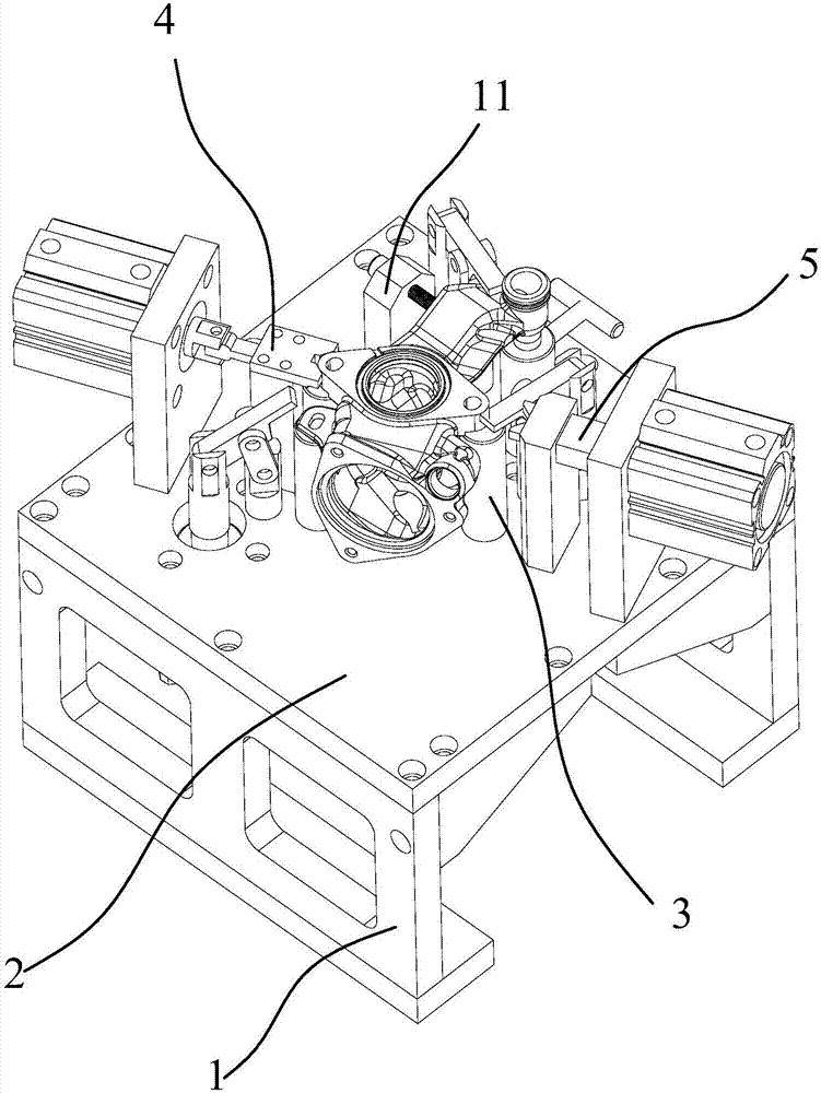
[0025] like Figure 2-8 As shown, the present invention provides a clamping tool for the lower casing of the engine thermostat, which includes a frame 1, a bottom plate 2 is arranged on the frame, and a positioning column 3, a horizontal clamping mechanism and a plurality of vertical clamps are arranged on the bottom plate 2. Straight pressing mechanism;

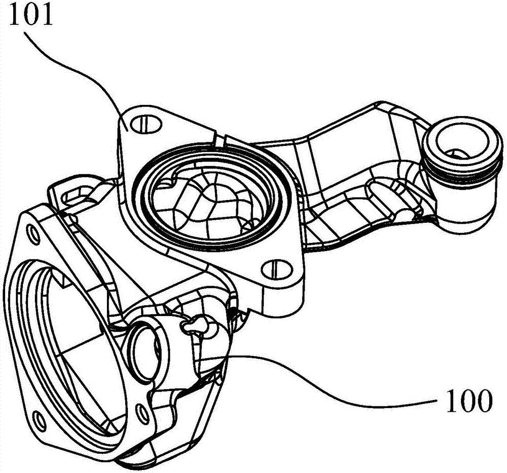
[0026] The positioning column 3 is fixed on the bottom plate 2, and is used to support the pre-processed product;

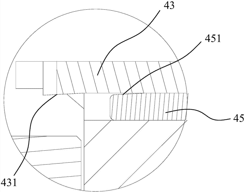
[0027] The horizontal clamping mechanism includes a first clamping device 4 and a second clamping device 5 oppositely arranged on the bottom plate 2, the first clamping device 4 includes a fixed seat 41 and a first support plate 42, and the top of the fixed seat 41 A V-shaped block 43 is provided, the first support plate 42 is fixedly connected with a first cylinder 44, the pi...


PUM


Abstract

The invention discloses a clamping tool for a lower shell of an engine thermostat. The clamping tool comprises a machine frame (1); a base plate (2) is arranged on the machine frame (1); positioning column (3), a horizontal clamping mechanism and a plurality of vertical pressing mechanisms are arranged on the base plate (2); the positioning columns (3) are used for supporting a product to be machined; a first clamping device (4) and a second clamping device (5) which are oppositely arranged are further fixedly arranged on the base plate (2) and are used for carrying out relative clamping and limiting on the two sides of the lower shell; the vertical pressing mechanisms are fixedly arranged on the base plate (2) in the circumferential direction of the product; and when the product is placedon the positioning columns (3), the horizontal pressing mechanism clamps and limits the product in the horizontal direction, and the vertical pressing mechanisms press and limit the product the vertical direction. The clamping tool for the lower shell of the engine thermostat has the advantages that, the positioning of the product in the horizontal direction is stable, the adjustment is convenient, and in addition, the occupied space is small.

Description

technical field [0001] The invention relates to the technical field of engine thermostats, in particular to a clamping tool for the lower casing of the engine thermostat. Background technique [0002] In the prior art, an engine cooling system is usually installed at the position of the automobile engine. The engine cooling system is used to reduce the temperature of the engine and ensure that the engine is in a suitable temperature range; prevent the engine from malfunctioning due to excessive temperature, or prevent the engine from Inefficiency due to low temperature. In order to achieve the above purpose, the engine cooling system usually includes a thermostat, which is an automatic temperature adjustment device, which can be regarded as a valve arranged on the coolant flow path for controlling the coolant flow. [0003] A thermostat usually includes a thermostat housing and a temperature sensing component. Among them, the thermostat housing includes a flange and a liqu...

Claims


Application Information

Patent Timeline
IPC IPC(8): B23Q3/08
CPCB23Q3/08
Inventor 胡松海厉超剑
Owner 宁波裕隆汽车制泵有限公司
Why Eureka
Try Eureka