Lift force device

A lift, large sprocket technology, used in helicopters, transportation and packaging, aircraft, etc., can solve problems such as unfavorable lift, failure, and difficulty in vertical lifting of flappers, and achieve high efficiency.

Inactive Publication Date: 2018-05-01
FOSHAN SHENFENG AVIATION SCI & TECH
View PDF9 Cites 0 Cited by
  • Summary
  • Abstract
  • Description
  • Claims
  • Application Information

AI Technical Summary

Problems solved by technology

[0002] At present, the flapping-wing aircraft has not yet reached the real practical stage, mainly because the traditional flapping-wing method is ineffective, which is not conducive to lift-off; the traditional flapping-wing aircraft is difficult to vertically lift

Method used


Image

  • Lift force device
  • Lift force device
  • Lift force device

Examples


Embodiment Construction

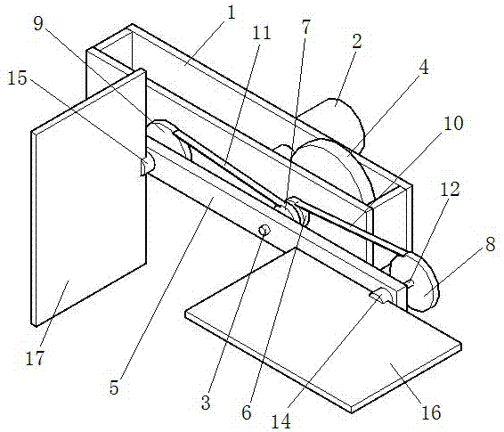
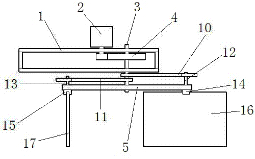
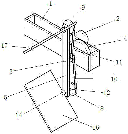
[0010] The present invention is now described in detail in conjunction with the accompanying drawings: a lift device, including a fixed frame 1, an engine 2, a main shaft 3, a large gear 4, a rotating arm 5, a first small sprocket 6, a second small sprocket 7, a first Large sprocket 8, second large sprocket 9, first chain 10, second chain 11, first traction shaft 12, second traction shaft 13, first fixing clip 14, second fixing clip 15, first blade 16 and the second blade 17. The main shaft 3 is installed on the fixed frame 1 through the bearing; the large gear 4 is installed on the main shaft 3; the middle part of the rotating arm 5 is fixed on the end of the main shaft 3; the power of the engine 2 is transmitted to the large gear 4 through the gear structure, and when the large gear 4 rotates The main shaft 3 drives the rotating arm 5 to rotate; the first small sprocket 6 and the second small sprocket 7 have the same structure; the first small sprocket 6 and the second small...


PUM


Abstract

The invention provides a lift force device and belongs to the technical field of aviation. The lift force device comprises a fixing frame, an engine, a main shaft, a large gear, a rotary arm, a firstsmall chain wheel, a second small chain wheel, a first large chain wheel, a second large chain wheel, a first chain, a second chain, a first traction shaft, a second traction shaft, a first fixing clamp, a second fixing clamp, a first blade and a second blade. The middle portion of the rotary arm is fixed to the main shaft. The engine drives the rotary arm to rotate, the ceaselessly-rotating rotary arm drives the first blade and the second blade to conduct flapping actions by turns at a certain inclination angle, wherein the first blade and the second blade are kept perpendicular to each otherall the time. When the blades conduct flapping motion, a relative high pressure region can be formed below the blades, a relative low pressure region can be formed above the blades, and upward lift force is generated on the blades. The lift force device is high in efficiency and can continuously generate lift force; and the lift force device is installed on an air vehicle, the air vehicle can take off vertically, and the lift force device can be used for exploration or scientific research.

Description

technical field [0001] A lift device belongs to the technical field of aviation, and in particular relates to a lift device. Background technique [0002] At present, the flapping-wing aircraft has not yet reached the real practical stage, mainly because the traditional flapping-wing method is ineffective, which is not conducive to lift-off; the traditional flapping-wing aircraft is difficult to lift vertically. Contents of the invention [0003] The purpose of the present invention is to overcome the above-mentioned deficiency of existing orthopter, invents a kind of device that can produce lift. [0004] A lifting device, including a fixed frame, an engine, a main shaft, a large gear, a rotating arm, a first small sprocket, a second small sprocket, a first large sprocket, a second large sprocket, a first chain, and a second chain , the first traction shaft, the second traction shaft, the first fixing clip, the second fixing clip, the first blade and the second blade. T...

Claims


Application Information

Patent Timeline
Patent Type & Authority Applications(China)
IPC IPC(8): B64C33/02
CPCB64C33/02
Inventor 王志成李玉龙
Owner FOSHAN SHENFENG AVIATION SCI & TECH
Why Eureka
Try Eureka