A surface resistance testing platform

A technology for testing platform and surface resistance, applied in the direction of measuring resistance/reactance/impedance, measuring device, measuring electrical variables, etc., can solve the problem of danger expansion and achieve the effect of preventing damage

Active Publication Date: 2020-02-18
浙江安迅电气股份有限公司
View PDF1 Cites 0 Cited by
  • Summary
  • Abstract
  • Description
  • Claims
  • Application Information

AI Technical Summary

Problems solved by technology

[0004] The purpose of the present invention is to overcome the above-mentioned problems in the prior art, and provide a surface resistance testing platform, which can cut off the power supply in time when the current is too large or the object under test is broken down, so as to avoid the expansion of danger

Method used


Image

  • A surface resistance testing platform
  • A surface resistance testing platform
  • A surface resistance testing platform

Examples


Embodiment Construction

[0021] The following will clearly and completely describe the technical solutions in the embodiments of the present invention with reference to the accompanying drawings in the embodiments of the present invention. Obviously, the described embodiments are only some, not all, embodiments of the present invention. Based on the embodiments of the present invention, all other embodiments obtained by persons of ordinary skill in the art without creative efforts fall within the protection scope of the present invention.

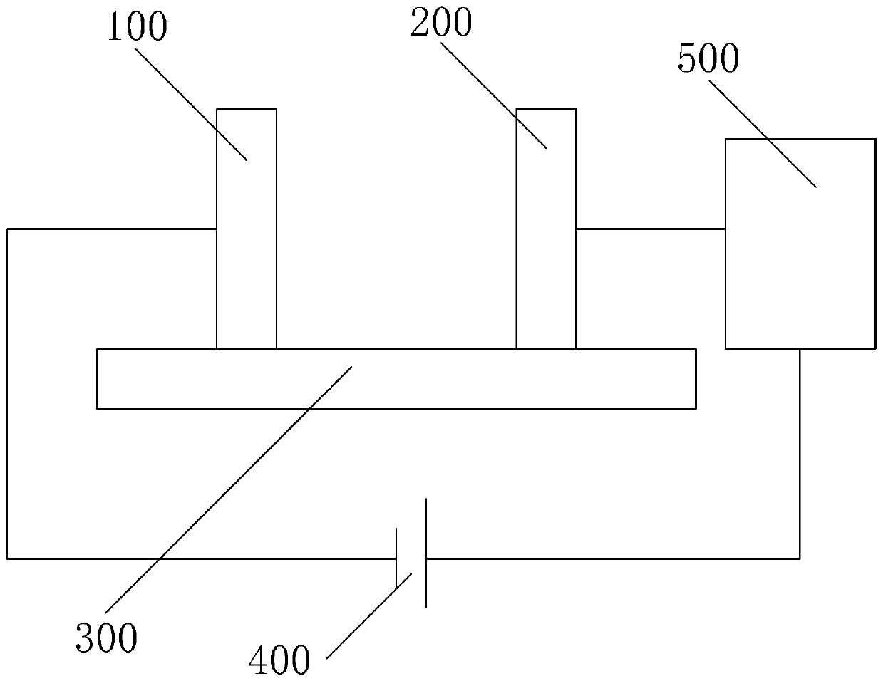
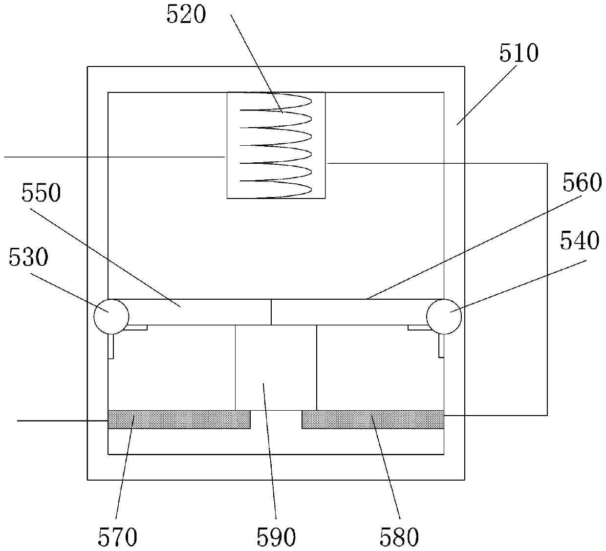
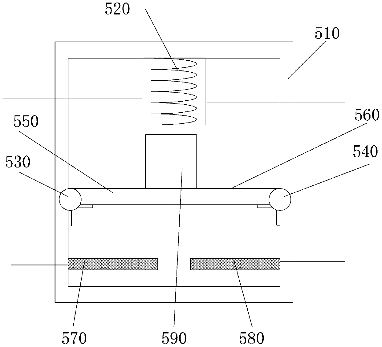
[0022] like Figure 1-4 As shown, the present invention is a surface resistance testing platform, comprising a first fixture pole plate 100 and a second fixture pole plate 200 oppositely arranged, and the first fixture pole plate 100 and the second fixture pole plate 200 are fixed on the test bench 300 On the upper surface, the test bench 300 is made of insulating material;

[0023] Both ends of the first fixture plate 100 and the second fixture plate 200 are elec...


PUM


Abstract

The invention discloses a surface resistance testing platform. The surface resistance testing platform comprises a first clamp polar plate and a second clamp polar plate which are arranged oppositely,wherein the first clamp polar plate and the second clamp polar plate are fixed on the upper surface of a testing table; and the testing table is made of an insulating material. In an implementing process, when a tested object is punctured, the current of an electromagnet is increased, the magnetic attraction force to an iron block is increased, the iron block overcomes the gravity thereof and thepressing force of a baffle, on the upper part of the baffle, electric connection between a first conductor block and a second conductor block is released, power supplied from a power supply to the clamp polar plates is also released, moreover, due to the effect of a twisting force of hinges of springs, the iron block cannot descend to be connected with the conductor blocks, and the power supply can be switched off in time under the condition that the tested object is punctured.

Description

technical field [0001] The invention relates to the field of surface resistance testing equipment, in particular to a surface resistance testing platform. Background technique [0002] Surface resistance is also called surface specific resistance. An important data characterizing the electrical properties of dielectric or insulating materials. It represents the resistance per square area of ​​the dielectric surface to the surface leakage current between the opposite sides of the square. [0003] A surface resistance test probe is disclosed in the patent with publication number CN105866548A, which is characterized in that it includes a plane and equal-thick insulation module (2), and the insulation module (2) is provided with four equidistant linear arrangements 1. The through holes (3) with the same aperture shape up and down, the same positions in the four through holes (3) are each provided with a metal wire (5) connected to the resistance test external circuit, and the ...

Claims


Application Information

Patent Timeline
Patent Type & Authority Patents(China)
IPC IPC(8): G01R27/02G01R1/36
CPCG01R1/36G01R27/02
Inventor 黄郁
Owner 浙江安迅电气股份有限公司
Why Eureka
Try Eureka