

Radio frequency antenna device
A technology of radio frequency antenna and antenna unit, which is applied in the field of radio frequency communication to avoid loss, ensure radiation efficiency, and avoid impedance mismatch.
- Summary
- Abstract
- Description
- Claims
- Application Information
AI Technical Summary
Problems solved by technology
Method used
Image


Examples
Embodiment Construction
[0022] In order to make the object, technical solution and advantages of the present invention clearer, the present invention will be further described in detail below in conjunction with the accompanying drawings and embodiments. It should be understood that the specific embodiments described here are only used to explain the present invention, not to limit the present invention.
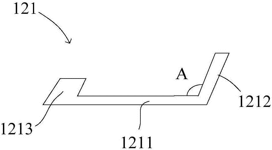
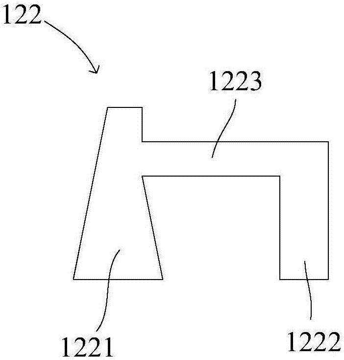
[0023] see Figure 1-3 , the radio frequency antenna device 1 according to the first embodiment of the present invention includes a substrate 11 and at least one antenna unit 12 disposed on the substrate 11; And spaced apart from the substrate 11 , one end of the conductor part 122 is connected to the radiation part 121 , and the other end is supported on the substrate 11 , and the width of at least a part of the conductor part 122 gradually increases along the direction away from the radiation part 121 . Wherein, the radiation part 121 is connected to the feed source and the ground through the co...
PUM
 Abstract
Description
Claims
Application Information