Clutch device with one driving mechanism and multiple driven mechanisms

A technology of clutch device and distance, applied in the direction of injection device, etc., can solve the problems of high cost, low production efficiency, and failure to meet industry requirements, etc., and achieve the effect of preventing free rotation and convenient use

Active Publication Date: 2018-05-04
JINING UNIV
View PDF6 Cites 5 Cited by
  • Summary
  • Abstract
  • Description
  • Claims
  • Application Information

AI Technical Summary

Problems solved by technology

Therefore, it is necessary to design a power separation and combination mechanism at the spraying station. After the product tooling on the painting, loading and unloading and drying station moves to the painting station, it can be combined with the prime mover of the spraying station. After the spraying operation is completed, it leaves the spraying station The front of the station can be separated from the original moving part of the spraying station. So far, the active mechanism and the driven mechanism in the clutch mechanism have a one-to-one correspondence, and the operating methods are mostly mechanical motor type and hydraulic type, which are applied to the rotary painting industry. The production efficiency is low, the cost is high, and the industry requirements cannot be met.

Method used


Image

  • Clutch device with one driving mechanism and multiple driven mechanisms
  • Clutch device with one driving mechanism and multiple driven mechanisms
  • Clutch device with one driving mechanism and multiple driven mechanisms

Examples


Embodiment Construction

[0027] The following will clearly and completely describe the technical solutions in the embodiments of the present invention with reference to the accompanying drawings in the embodiments of the present invention. Obviously, the described embodiments are only some, not all, embodiments of the present invention. Based on the embodiments of the present invention, all other embodiments obtained by persons of ordinary skill in the art without making creative efforts belong to the protection scope of the present invention.

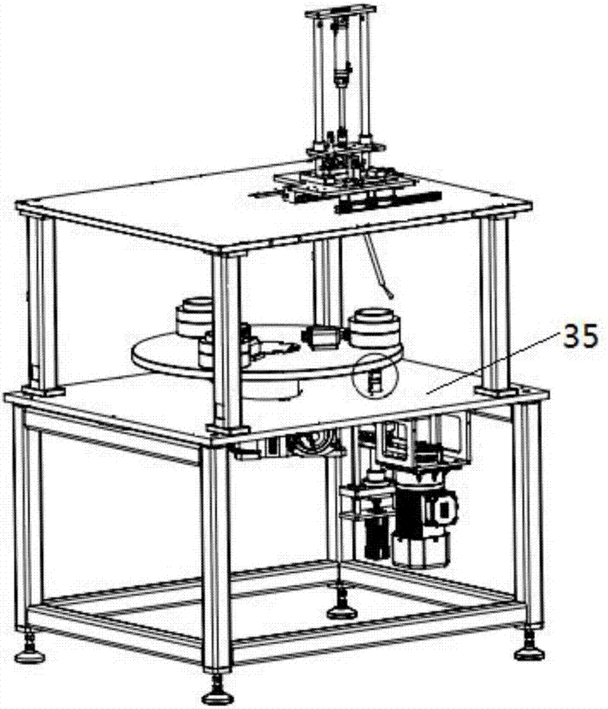
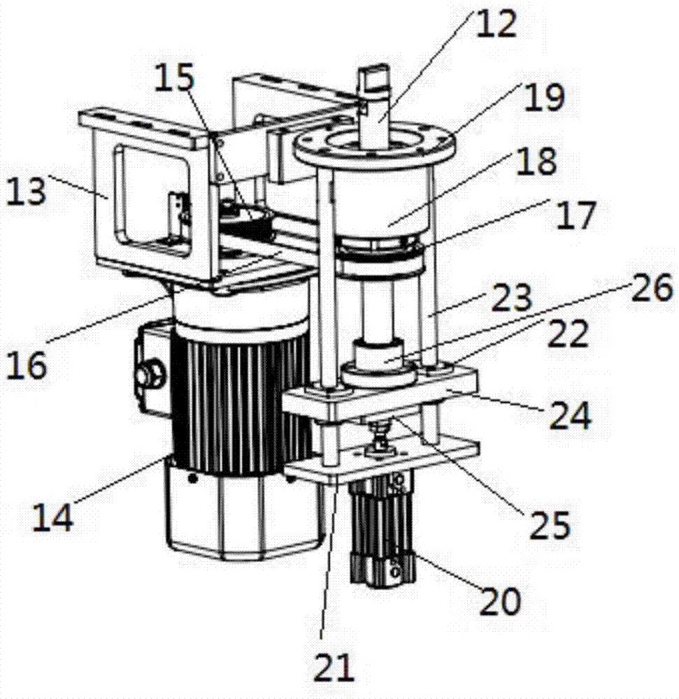
[0028] The purpose of the present invention is to provide a one-master multi-slave clutch device to solve the above-mentioned problems in the prior art, realize automatic and continuous painting of products, and improve production efficiency.

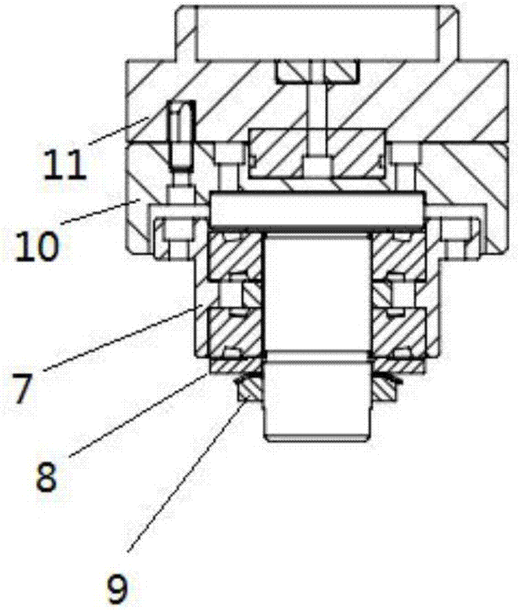
[0029] A master multi-slave clutch device provided by the present invention includes a rotary table, three shaft holes at equal intervals are opened on the rotary table, and the three shaft holes of the rotary table are ...


PUM


Abstract

The invention discloses a clutch device with one driving mechanism and multiple driven mechanisms. The clutch device comprises a rotary table plate. Three equal-interval shaft holes are formed in therotary table plate, and the driven mechanisms are arranged in the three shaft holes of the rotary table plate correspondingly. Rotary shafts of the driven mechanisms are movably arranged in the shaftholes in a penetrating mode, and the driving mechanism and a manipulating mechanism are fixed to the lower portion of the rotary table plate. The horizontal displacement of a rotary shaft of the driving mechanism from the center of the rotary table plate is equal to the horizontal displacement of the rotary shafts of the driven mechanisms from the center of the rotary table plate. The manipulatingmechanism controls the rotary shaft of the driving mechanism to move up and down, and a block-shaped protrusion is arranged at the top of the rotary shaft of the driving mechanism. Grooves matched with the block-shaped protrusion are formed in the bottoms of the rotary shafts of the driven mechanisms. According to the clutch device with one driving mechanism and the multiple driven mechanisms, product automatic continuous paint spraying operation is achieved, and the production efficiency is improved.

Description

technical field [0001] The invention relates to the technical field of clutch mechanisms in the rotary painting industry, in particular to a one-master multi-slave clutch device. Background technique [0002] In the rotary spray painting industry, the product to be sprayed is the inner surface or the outer surface of the cylinder. There are two ways to spray: 1. The spray gun is fixed and the product is rotated; 2. The spray gun is rotated and the product is fixed. The air pipe and other connections are usually sprayed with the spray gun fixed and the product rotated. During the spraying operation, the product rotates under the power drive. At the same time, in order to realize the automatic operation of the spraying work and the continuity of production, it is required to design multiple stations to realize product loading and unloading, spraying and drying paint, etc. The bottom is rotated, while the products on other stations do not rotate. Therefore, it is necessary to...

Claims


Application Information

Patent Timeline
IPC IPC(8): B05B13/02B05B13/06
CPCB05B13/0228B05B13/0609B05B13/0645
Inventor 王兆艳刘军
Owner JINING UNIV
Why Eureka
Try Eureka