Positioning stamping die

A technology of stamping dies and dies, applied in the field of dies, can solve problems such as workpiece movement, achieve the effect of ensuring quality and avoiding secondary processing

Inactive Publication Date: 2018-05-04
重庆市合川区云天机械制造有限公司
View PDF9 Cites 2 Cited by
  • Summary
  • Abstract
  • Description
  • Claims
  • Application Information

AI Technical Summary

Problems solved by technology

[0004] The present invention intends to provide a positioning stamping die to solve the problem of workpiece movement during the stamping process

Method used


Image

  • Positioning stamping die
  • Positioning stamping die
  • Positioning stamping die

Examples


Embodiment Construction

[0023] The following is further described in detail through specific implementation methods:

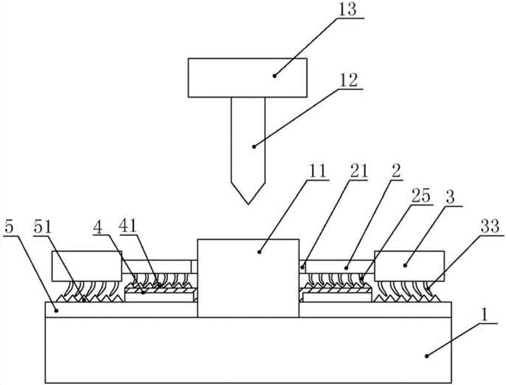
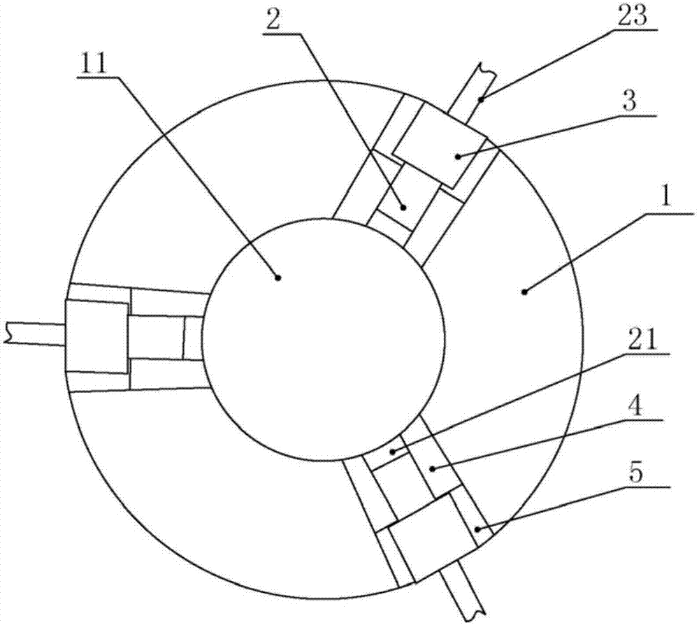
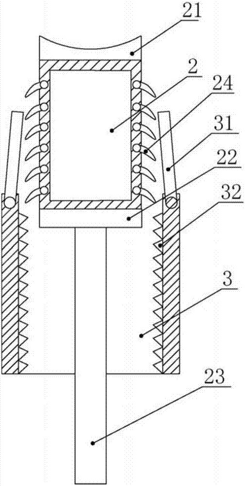
[0024] The reference signs in the accompanying drawings of the specification include: lower die 1, workpiece 11, stamping head 12, upper die 13, second clamping rod 2, clamping block 21, push plate 22, push rod 23, second pawl 24 , the third pawl 25, the first clamping rod 3, the baffle plate 31, the third fixed tooth 32, the first pawl 33, the second fixed plate 4, the second fixed tooth 41, the first fixed plate 5, the first Fixed tooth 51.

[0025] Such as figure 1 and figure 2 As shown, a positioning stamping die of the present invention includes an upper die 13, a stamping head 12 is connected below the upper die 13, a circular lower die 1 is installed under the punching head 12, and three first fixed dies are evenly installed on the lower die 1. Plate 5, the first fixed plate 5 is arranged along the radial direction of the lower mold 1, and the upper surface of the first fi...


PUM


Abstract

The invention relates to a die, in particular to a positioning stamping die. The positioning stamping die comprises an upper die, wherein a stamping head is connected under the upper die, and a lowerdie is arranged below the stamping head; a plurality of first fixing plates are arranged on the lower die, and a plurality of first fixing teeth are arranged on the upper surface of each first fixingplate; a plurality of first clamping rods are movably arranged on the outer side of the lower die, a plurality of first pawls which can be matched with the first fixing teeth are arranged at the bottoms of the first clamping rods, and the side walls of the ends, close to the first fixing plates, of the first clamping rods are hinged to baffles; a plurality of third fixing teeth are arranged on theinner walls of the first clamping rods, and second clamping rods are arranged in the first clamping rods in a sliding mode; and second pawls capable of being matched with the third fixing teeth are arranged on the two sides of the second clamping rods, and a plurality of third pawls which can be matched with the second fixing teeth are arranged at the bottoms of the second clamping rods. According to the positioning stamping die, the problem that a workpiece can move in the stamping process is solved.

Description

technical field [0001] The invention relates to a mold, in particular to a positioning stamping mold. Background technique [0002] Stamping is a pressure processing method that uses a mold installed on a press to apply pressure to the material at room temperature to cause separation or plastic deformation to obtain the required parts. [0003] During the stamping process, the workpiece will be moved by the impact force of the stamping head, causing the stamped shape of the workpiece to deviate from the expected shape. At the same time, the workpiece is also prone to warping, which requires secondary processing of the workpiece, which increases the processing cost and reduces the processing cost. efficiency. In addition, most of the existing stamping dies can only stamp one type of workpiece, and the utilization rate of the stamping die is low. When different workpieces need to be stamped, different stamping dies need to be switched, and the cost is high. Contents of the ...

Claims


Application Information

Patent Timeline
Patent Type & Authority Applications(China)
IPC IPC(8): B21D43/00B21D22/02
CPCB21D43/003B21D22/02
Inventor 张科
Owner 重庆市合川区云天机械制造有限公司
Why Eureka
Try Eureka