Plasma cutting table

A plasma and cutting table technology, applied in plasma welding equipment, welding/cutting auxiliary equipment, auxiliary devices, etc., can solve the problems of low precision, low yield, time-consuming and labor-intensive problems

Pending Publication Date: 2018-05-04
安陆市盛鑫风机有限公司
View PDF8 Cites 0 Cited by
  • Summary
  • Abstract
  • Description
  • Claims
  • Application Information

AI Technical Summary

Problems solved by technology

[0002] In the processing technology of the impeller, it is necessary to cut the rim of the impeller. In the past, the impeller was cut with a plasma cutting gun by hand. This processing method is not accurate, time-consuming and laborious, and the yield is low. , it is necessary to develop a plasma cutting table that can automatically complete this process

Method used


Image

  • Plasma cutting table
  • Plasma cutting table

Examples


Embodiment Construction

[0021] The principles and features of the present invention are described below in conjunction with the accompanying drawings, and the examples given are only used to explain the present invention, and are not intended to limit the scope of the present invention.

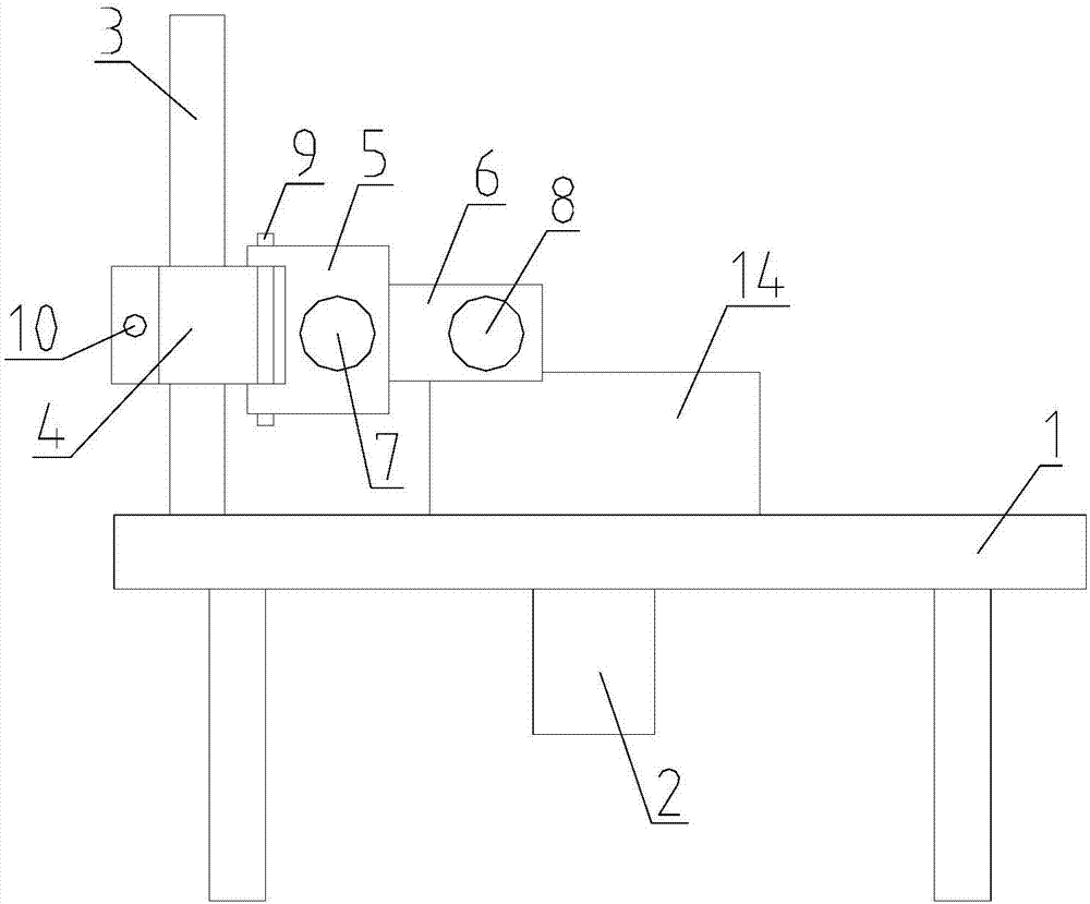
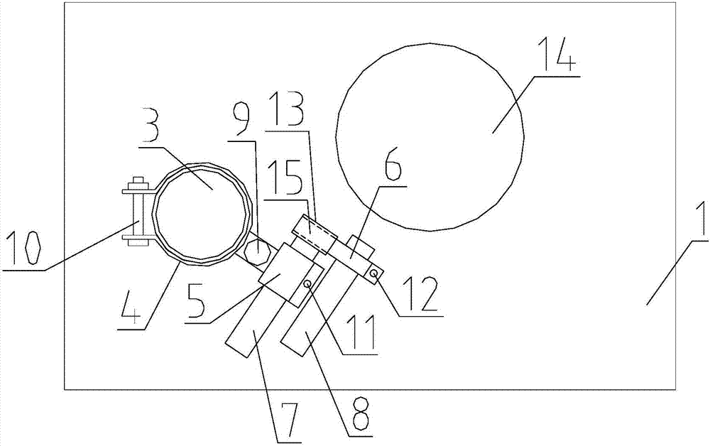
[0022] Such as figure 1 with 2 As shown, a plasma cutting table includes a frame 1, a column 3, a height adjustment block 4, an adjustment block one 5, an adjustment block two 6, an adjustment rod 7, and a plasma cutting gun 8. The lower part of the frame 1 is provided with a In the drive mechanism that drives the impeller 14 that is located at the top of the frame 1 to rotate, the column 3 is vertically arranged and its bottom end is fixedly connected to the top of the frame 1, and the height adjustment block 4 can be rotated around the The axis of the column 3 is rotated and positioned and can be moved and positioned in the vertical direction. The adjustment block 5 is rotatably connected with the height adjustme...


PUM


Abstract

The invention relates to a plasma cutting table. The plasma cutting table comprises a machine frame, a vertical column, a height adjusting block, a first adjusting block, a second adjusting block, anadjusting rod and a plasma cutting gun. A driving mechanism used for driving an impeller on the upper portion of the machine frame to rotate is arranged on the lower portion of the machine frame, thevertical column is vertically arranged, and the bottom end of the vertical column is fixedly connected to the upper portion of the machine frame. The height adjusting block can rotate around the axisof the vertical column, can position and can move in the vertical direction and position, the first adjusting block is rotatably connected with the height adjusting block, a through hole used for clamping the adjusting rod in the horizontal direction is formed in the first adjusting block, and the adjusting rod penetrates through the interior of the through hole of the first adjusting block and can move in the axial direction of the through hole and position. One end of the second adjusting block is rotatably connected to the adjusting rod, the second adjusting block can rotate around the axisof the adjusting rod and position, the other end of the second adjusting block clamps the plasma cutting gun, and the plasma cutting gun is connected with a plasma generation device. The plasma cutting table has the beneficial effect that cutting of the impeller edge of the impeller can be automatically completed.

Description

technical field [0001] The invention relates to impeller processing equipment, in particular to a plasma cutting table. Background technique [0002] In the processing technology of the impeller, it is necessary to cut the rim of the impeller. In the past, the impeller was cut with a plasma cutting gun by hand. This processing method is not accurate, time-consuming and labor-intensive, and the yield is low. , it is necessary to develop a plasma cutting table that can automatically complete this process. Contents of the invention [0003] The technical problem to be solved by the present invention is to provide a plasma cutting table, which can automatically complete the cutting at the rim of the impeller. [0004] The technical solution of the present invention to solve the above-mentioned technical problems is as follows: a plasma cutting table, including a frame, a column, a height adjustment block, an adjustment block 1, an adjustment block 2, an adjustment rod, and a ...

Claims


Application Information

Patent Timeline
Patent Type & Authority Applications(China)
IPC IPC(8): B23K10/00B23K37/02
CPCB23K10/00B23K37/0241
Inventor 毛传友何明智
Owner 安陆市盛鑫风机有限公司
Why Eureka
Try Eureka