Automobile wire harness fixer

A technology of automotive wiring harnesses and fixers, which is applied to vehicle components, circuits or fluid pipelines, transportation and packaging, etc., can solve problems such as shaking, wear, and hidden quality problems, and achieve good protection of wires, improved safety, and good durability Effect

Inactive Publication Date: 2018-05-04
唐世奎
0 Cites 3 Cited by

AI-Extracted Technical Summary

Problems solved by technology

At present, with the development of the automobile manufacturing industry, various control systems of automobiles are also more advanced, and various control circuits are becoming more and more complex. The automobile needs a large number of wiring to form a complete circuit system. Most of the automobile wiring harnesses are fixed by buckles. The method can only f...

Method used

In addition, described middle fixed seat 2 is provided with a plurality of, and adjacent middle fixed seat 2 is snapped together with draw-in groove 6 by the snap hook 5 that is set up relatively, can increase middle fixed seat according to the number of wire harnesses The number of 2 further increases the number of wire harness slots, makin...

Abstract

The invention discloses an automobile wire harness fixer and relates to the technical field of automobile parts. The automobile wire harness fixer comprises a left fixing seat, a middle fixing seat and a right fixing seat. First wire harness grooves are formed in the left fixing seat; the left fixing seat is connected with clamping grooves of the middle fixing seat through clamping hooks; second wire harness grooves are formed in the middle fixing seat; the middle fixing seat is connected with clamping grooves of the right fixing seat through clamping hooks; and third wire harness grooves areformed in the right fixing seat. Wire harnesses can be fixed stably, durability is good, the using safety of the wire harnesses is promoted greatly, practicability is high, and using and popularizingare easy.

Application Domain

Technology Topic

Image

  • Automobile wire harness fixer
  • Automobile wire harness fixer

Examples

  • Experimental program(1)

Example Embodiment

[0013] In order to make the technical means, creative features, objectives and effects of the present invention easy to understand, the present invention will be further explained below in conjunction with specific embodiments.
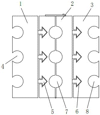
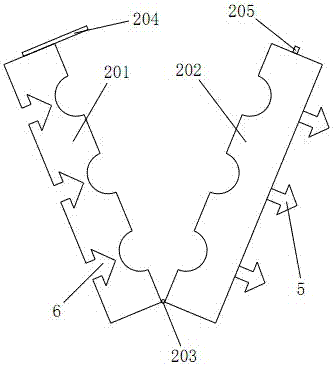
[0014] Reference Figure 1-2 , This specific embodiment adopts the following technical solutions: an automobile wire harness fixator, including a left fixing seat 1, a middle fixing seat 2, a right fixing seat 3, the left fixing seat 1 is provided with a first harness slot 4, and the left fixing seat 1 The hook 5 is connected to the groove 6 of the middle fixing base 2, and the middle fixing base 2 is provided with a second harness groove 7, and the middle fixing base 2 is connected to the groove 6 of the right fixing base 3 through the hook 5, and the right fixing base 3 is provided with a third wire harness slot 8; the card slots 6 in the holder all adopt the same specifications, and the hooks 5 also adopt the same specifications.
[0015] It is worth noting that there are a plurality of the first wire harness slot 4 and the third wire harness slot 8 provided, and the first wire harness slot 4 and the third wire harness slot 8 are respectively provided on the side walls of the left fixing seat 1 and the right fixing seat 3. , It is very convenient to install wires.
[0016] In addition, the middle fixing seat 2 is provided with multiple, and the adjacent middle fixing seat 2 is connected to the card slot 6 by the hooks 5 arranged oppositely. According to the number of wire harnesses, the number of the middle fixing seat 2 can be increased. In turn, the number of wiring harness slots is increased and the use is more flexible.
[0017] The central fixing base 2 of this specific embodiment adopts the link structure of the first mounting part 201 and the second mounting part 202. The first mounting part 201 and the second mounting part 202 are connected as a whole through the bottom shaft 203, and the first mounting part 201 passes through the top part. The buckle 204 is buckled with the buckle ring 205 on the top of the second mounting portion 202. The grooves of the first mounting portion 201 and the second mounting portion 202 opposite to each other are formed with a second harness groove 7 and a card slot on the first mounting portion 201 6 corresponds to the position of the hook 5 on the second mounting portion 202 and matches the shape.
[0018] When this specific embodiment is used, first determine the number of middle fixing bases 2 according to the number of wire harnesses, and then fix one of the middle fixing bases 2 to the slot 6 of the other middle fixing base 2 through the hook 5, and so on. Then connect the left fixing seat 1 and the right fixing seat 3 on both sides to the left and right sides of the integrated middle fixing seat 2 through the hook 5 and the card slot 6 respectively; clamp the wire on the left side of the wiring harness into the left and fix it In the first wire harness slot 4 of the base 1, the wires on the right side of the wire harness are clamped into the third wire harness slots 8 of the right fixing base 3. The remaining wires are arranged in order and placed in the second wire harness slot 7, and finally connected with the fastener 204 The buckle ring 205 can be buckled and fixed.
[0019] This specific implementation is very flexible and convenient for fixing automobile wiring harnesses. It not only enables a large number of wiring harnesses to be effectively and rationally arranged in a limited automobile space, but also enables automobile wiring harnesses to exert greater functions, stability and reliability, and higher safety in use. Market application prospects.
[0020] The basic principles and main features and advantages of the present invention have been shown and described above. Those skilled in the industry should understand that the present invention is not limited by the foregoing embodiments. The foregoing embodiments and descriptions only illustrate the principles of the present invention. Without departing from the spirit and scope of the present invention, the present invention may have Various changes and improvements, these changes and improvements fall within the scope of the claimed invention. The scope of protection claimed by the present invention is defined by the appended claims and their equivalents.

PUM

no PUM

Description & Claims & Application Information

We can also present the details of the Description, Claims and Application information to help users get a comprehensive understanding of the technical details of the patent, such as background art, summary of invention, brief description of drawings, description of embodiments, and other original content. On the other hand, users can also determine the specific scope of protection of the technology through the list of claims; as well as understand the changes in the life cycle of the technology with the presentation of the patent timeline. Login to view more.

Similar technology patents

Automatic Wheel Chock System

InactiveUS20140188334A1Easy to install and useBraking element arrangementsPortable braking systemWheel chockActuator
Owner:FOSTER CHRISTOPHER R

Classification and recommendation of technical efficacy words

  • Easy to install and use
  • Fixed firmly

Rise up table top

Owner:WEST VIRGIL J +1

Flexible fixing plate for acromioclavicular joint

ActiveCN104116553AFixed firmlyEasy installation and positioningBone platesSteel platesSacroiliac joint
Owner:BIODA DIAGNOSTICS WUHAN
Why Eureka
Try Eureka