Plastic electronic tray

An electronic tray and tray technology, applied in the electronic field, can solve the problems of low operating efficiency of electronic chips, inability to place both front and back sides and fast flipping, etc., so as to achieve the goal of not easy to scatter, reduce the vacuuming process, and improve production efficiency Effect

Inactive Publication Date: 2018-05-04
东台市环球塑料制品有限公司
View PDF7 Cites 0 Cited by
  • Summary
  • Abstract
  • Description
  • Claims
  • Application Information

AI Technical Summary

Problems solved by technology

[0003] The technical problem to be solved by the present invention is to overcome the defects that the traditional electronic chip packaging and transportation tray can only realize the function of single-sided use, cannot satisfy the functions of both the front and back sides can be placed and quickly flipped, and the operation efficiency is not high on the electronic chip assembly line, and provides A plastic electronic tray

Method used


Image

  • Plastic electronic tray

Examples


Embodiment 1

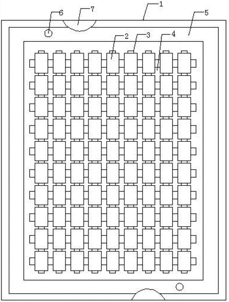
[0016] like figure 1 As shown, the present invention provides a plastic electronic tray, comprising a tray main body 1, the front of the tray main body 1 is divided into several evenly distributed electronic chip placement platforms 2 by several uniformly distributed forward protrusions 3, and the back side of the tray main body 1 A number of uniformly distributed electronic chip placement platforms 2 are separated by a number of evenly distributed reverse protrusions 4. The outer ring of the tray body 1 is provided with overlapping concave grooves 5, and the electronic chip placement platforms 2 on the front and back sides of the tray body 1 are one by one. Correspondingly, the positive protrusions 3 are evenly distributed on the four sides of the electronic chip placement platform 2, and the reverse protrusions 4 are evenly distributed on the four corners of the electronic chip placement platform 2. The bottom of the tray is provided with a threaded groove, and the box body ...


PUM


Abstract

The invention discloses a plastic electronic tray. The plastic electronic tray comprises a tray body; the front surface of the tray body is divided into multiple electronic chip placing platforms, uniformly distributed, by multiple forward projections uniformly distributed; the back surface of the tray body is divided into multiple electronic chip placing platforms, uniformly distributed, by multiple reverse projections uniformly distributed; an overlapped concave groove is formed in an outer ring of the tray body; the electronic chip placing platforms on the front and reverse surfaces of thetray body are corresponding one to one; the forward projections are uniformly distributed on four edges of the electronic chip placing platforms; and the reverse projections are uniformly distributedat four corners of the electronic chip placing platforms. Electronic chips can be placed on the front and reverse surfaces of the device; the front and reverse surfaces can be quickly operated in a precision range of a mechanical arm; the loaded electronic chips can be quickly overturned between upper and lower plastic electronic trays to realize quick overturning of whole stacks so as to greatlyimprove the production efficiency; and in the transportation process, the electronic chips are not easy to scatter, so that the vacuumizing process is reduced.

Description

technical field [0001] The invention relates to a tray, in particular to a plastic electronic tray, which belongs to the technical field of electronics. Background technique [0002] Traditional electronic chip packaging and transportation trays can only be used on one side, and cannot be placed on both sides and quickly turned over. The operation efficiency on the electronic chip assembly line is not high. Contents of the invention [0003] The technical problem to be solved by the present invention is to overcome the defects that the traditional electronic chip packaging and transportation tray can only realize the function of single-sided use, cannot satisfy the functions of both the front and back sides can be placed and quickly flipped, and the operation efficiency is not high on the electronic chip assembly line, and provides A plastic electronic tray. [0004] In order to solve the problems of the technologies described above, the present invention provides the fol...

Claims


Application Information

Patent Timeline
Patent Type & Authority Applications(China)
IPC IPC(8): B65D19/44B65D19/38
CPCB65D19/44B65D19/38B65D2519/00034
Inventor 钱尧
Owner 东台市环球塑料制品有限公司
Why Eureka
Try Eureka