Anti-falling mechanism in case of breakage of crane hook steel wire rope

A wire rope and crane technology, applied in the field of hoisting machinery moving pulley device, can solve the problems of casualties, unbearable load, equipment damage, etc., and achieve the effects of avoiding falling incidents, reasonable structure and low operating cost

Inactive Publication Date: 2018-05-04
德马科起重机械有限公司
View PDF6 Cites 5 Cited by
  • Summary
  • Abstract
  • Description
  • Claims
  • Application Information

AI Technical Summary

Problems solved by technology

[0002] The pick-up device of the hoisting machinery is generally composed of pulleys or pulley blocks and hooks, cages, electromagnetic suckers, vacuum suckers, grabs and other pick-up mechanisms. The lifting wire rope is connected to the lifting drive mechanism of the hoisting machinery through the pulley device. Make the pick-up device lift or lower the heavy objects. When the hoisting wire rope on one side accidentally loosens or breaks during the lifting of the heavy objects, the wire rope on this side can

Method used


Image

  • Anti-falling mechanism in case of breakage of crane hook steel wire rope

Examples


Embodiment 1

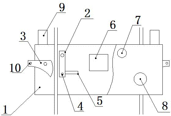
[0014] Such as figure 1 As shown, a crane hook wire rope broken rope anti-falling mechanism, it includes a wire rope splint 1, the steel wire rope splint 1 is respectively connected with a movable jaw 2 and an engaging tooth 3 matched with the movable jaw 2 through a pin shaft, The lower part of the movable jaw 2 is provided with a locking hole 4, and the lower part of the movable jaw 2 is connected with an electric push rod 5, and the described electric push rod 5 is connected with a controller 6 through a signal line, and the described controller 6 Connect with the wire rope splint 1 by bolts, the output end of the controller 6 is respectively connected with the alarm 7 and the electromagnetic lock 8 matched with the movable jaw 2 through the signal line, and the alarm 7 and the electromagnetic lock 8 are all arranged on the wire rope On the outer wall of the splint 1 , the input end of the controller 6 is connected with a speed measuring device 9 through a signal line, and ...

Embodiment 2

[0017] Such as figure 1 As shown, a crane hook wire rope broken rope anti-falling mechanism, it includes a wire rope splint 1, the steel wire rope splint 1 is respectively connected with a movable jaw 2 and an engaging tooth 3 matched with the movable jaw 2 through a pin shaft, The lower part of the movable jaw 2 is provided with a locking hole 4, and the lower part of the movable jaw 2 is connected with an electric push rod 5, and the described electric push rod 5 is connected with a controller 6 through a signal line, and the described controller 6 Connect with the wire rope splint 1 by bolts, the output end of the controller 6 is respectively connected with the alarm 7 and the electromagnetic lock 8 matched with the movable jaw 2 through the signal line, and the alarm 7 and the electromagnetic lock 8 are all arranged on the wire rope On the outer side wall of the splint 1, the input end of the controller 6 is connected with a speed measuring device 9 through a signal line, ...


PUM


Abstract

The invention relates to an anti-falling mechanism in case of breakage of a crane hook steel wire rope. The anti-falling mechanism comprises steel wire rope clamping plates which are separately connected to moving jaws and occlusion teeth matched with the moving jaws through hinge pins, and the lower parts of the moving jaws are provided with locking holes, and connected to electric linear actuators connected to controllers through signal lines; the controllers are connected to the steel wire rope clamping plates by bolts, and the output ends of the controllers are separately connected to an alarm and an electromagnetic lock matched with the moving jaws through the signal lines; the alarm and the electromagnetic lock are both arranged on the outer side walls of the steel wire rope clampingplates, and the input ends of the controllers are connected to speed measuring devices through the signal lines; the speed measuring devices are arranged on the upper ends of the steel wire rope clamping plates; and the occlusion teeth are provided with connecting holes. The anti-falling mechanism has the advantages of rational structure, easy use, high safety and low operation cost.

Description

technical field [0001] The invention belongs to the technical field of moving pulley devices of hoisting machinery, and in particular relates to a wire rope breakage prevention mechanism for crane hooks and wire ropes. Background technique [0002] The pick-up device of the hoisting machinery is generally composed of pulleys or pulley blocks and hooks, cages, electromagnetic suckers, vacuum suckers, grabs and other pick-up mechanisms. The lifting wire rope is connected to the lifting drive mechanism of the hoisting machinery through the pulley device. Make the pick-up device lift or lower the heavy objects. When the hoisting wire rope on one side accidentally loosens or breaks during the lifting of the heavy objects, the wire rope on this side cannot bear the load. Therefore, the heavy objects follow the pulley hook together Falling at the speed of free fall causes accidents such as casualties and equipment damage. This kind of falling accident caused by the breaking of the ...

Claims


Application Information

Patent Timeline
IPC IPC(8): B66C1/34B66C15/02
CPCB66C1/34B66C15/02
Inventor 董彦波丁一董爱军
Owner 德马科起重机械有限公司
Why Eureka
Try Eureka