Infrared lens with high definition, long focal length and long wave

A long-wave infrared and long focal length technology, applied in the field of infrared lenses, can solve the problems of inability to achieve long focal length and large zoom ratio infrared lenses, inability to match high-resolution high-definition detectors, and difficulty in designing high-resolution zoom ratios. Achieve the effect of reducing the number of lenses, improving the recognition ability, and high transmittance

Active Publication Date: 2018-05-04
山东神戎电子股份有限公司
View PDF34 Cites 7 Cited by
  • Summary
  • Abstract
  • Description
  • Claims
  • Application Information

AI Technical Summary

Problems solved by technology

The uncooled long-wave continuous zoom lens in the prior art has defects such as small zoom ratio, short focal length, large F-number, and low resolution of the matching detector. With the rapid development of the industry, infrared detector manufacturers have launched 1024×768, 1280×1280 high-resolution high-definition detectors one after another. However, most of the lenses on the market are designed based on low-resolution detectors and have no connection with high-resolution detectors. Infrared lens with long focal length and large zoom ratio matched with the sensor
The ultra-large zoom ratio continuous zoom infrared lens disclosed in Chinese patent document CN201410094484 cannot match high-resolution high-definition detectors (1024 and above), which is severely limited in high-performance applications
And CN201510253987 discloses a kind of continuous zoom infrared lens that adopts a five-lens mirror system, which cannot realize a large zoom ratio infrared lens with a long focal length
According to the above limitations, it is very difficult to design long focal length, large zoom ratio and high resolution

Method used


Image

  • Infrared lens with high definition, long focal length and long wave
  • Infrared lens with high definition, long focal length and long wave
  • Infrared lens with high definition, long focal length and long wave

Examples


Embodiment Construction

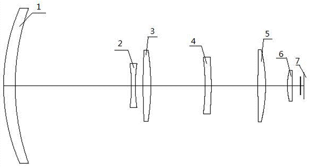
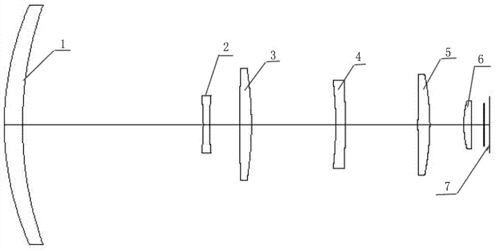
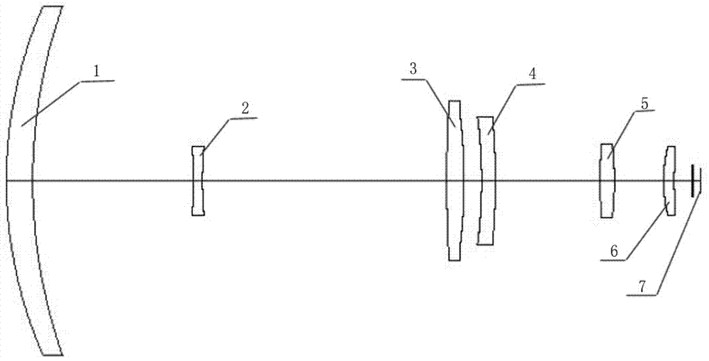
[0025] The present invention will be further described below in conjunction with the accompanying drawings and specific embodiments.

[0026] Such as figure 1 , figure 2 and image 3As shown, the optical system diagrams of the high-definition long-focus long-wave infrared lens of the present invention at focal lengths of 300mm, 150mm, and 25mm are given. group, variable magnification group, compensation group, rear fixed group and detector 7, and the front fixed group is composed of a positive meniscus lens 1 with a convex surface facing the object side, so as to realize the converging effect on the incident light. The variable power group is composed of a biconcave lens 2, and the compensation group is composed of a first biconvex lens 3. The zooming of the lens is realized through the movement of the biconcave lens 2, and the biconvex lens 3 cooperates with the movement to compensate for the offset of the image plane during the zooming process, so as to obtain clear infr...


PUM


Abstract

The invention discloses an infrared lens with high definition, long focal length and long wave. The infrared lens comprises a front fixed group, a zooming group, a compensating group, a rear fixed group and a detector which are sequentially distributed along an optical axis from the object side to the image side, wherein the front fixed group consists of positive meniscus lenses of which convex surfaces face to the object side; the zooming group consists of biconcave lenses; the compensating group consists of first double convex lenses; the rear fixed group consists of a first negative meniscus lens, a second biconvex lens and a second negative meniscus lens which are sequentially distributed along the incidence direction of light. The infrared lens disclosed by the invention has the advantages that continuous zooming of high zooming ratio (25 to 300mm) can be realized, and a target is found at short focus and is identified at long focus; in addition, the target cannot be lost in the zooming process; the infrared lens can be matched with infrared detectors with high-definition, big area array and long wave and types of 1024*768 and 1280*1280.

Description

technical field [0001] The invention relates to an infrared lens, specifically, a high-definition long-focus long-wave infrared lens. Background technique [0002] The infrared thermal imaging system has many advantages such as good concealment, strong anti-electronic interference ability, intuitive image, easy observation, high precision, and good low-altitude detection performance. The ability to identify camouflage is especially suitable for the detection of targets at night and under complex weather conditions. It has broad application prospects in the fields of warning, reconnaissance and security, and has attracted increasing attention from various scientific research institutions and enterprises. Compared with cooled staring infrared thermal imagers, although there is still a big gap in sensitivity such as temperature resolution, uncooled has some outstanding advantages, such as no need to cool the detector, greatly reduced device cost, power consumption Small, light...

Claims


Application Information

Patent Timeline
Patent Type & Authority Applications(China)
IPC IPC(8): G02B15/167
CPCG02B15/167
Inventor 徐仰惠马兴才于兴
Owner 山东神戎电子股份有限公司
Why Eureka
Try Eureka