Drive method of liquid crystal display device

A technology of a liquid crystal display device and a driving method, which is applied to static indicators, instruments, etc., to achieve the effect of avoiding flickering and displaying uniform brightness

Active Publication Date: 2018-05-04
WUHAN CHINA STAR OPTOELECTRONICS TECH CO LTD
View PDF4 Cites 15 Cited by
  • Summary
  • Abstract
  • Description
  • Claims
  • Application Information

AI Technical Summary

Problems solved by technology

[0006] However, during the driving process of the above-mentioned liquid crystal display device, for the pixel 100' in the mth row, the voltage on the pixel electrode 111' of the sub-pixel 110' connected to the first thin film transistor T1' will be in the first multiplexed When the signal MUX1' changes from a high potential to a low potential, a first voltage difference is dropped, and when the potential of the mth scanning line G(m)' changes from a high potential to a low potential, a second voltage difference is dropped The voltage on the pixel electrode 111' of the sub-pixel 110' connected to the second thin film transistor T2' will drop by the first voltage difference when the second multiplexing signal MUX2' changes from a high potential to a low potential, and When the potential of the m-th scanning line G(m)' changes from a high potential to a low potential, the second voltage difference is reduced, and the sub-pixel 110' electrically connected to the third thin film transistor T3' in the even-numbered column pixel 100' The voltage on the pixel electrode 111' of the pixel electrode 111' will also reduce the first voltage difference and the second voltage difference, but the pixel electrode 111 of the sub-pixel 110' electrically connected to the third thin film transistor T3' in the odd-numbered column pixel 100' ' will only reduce the second voltage difference, which causes the voltage drop on the pixel electrode 111' of each sub-pixel 110' in the same row of pixels 100' to be different, and will have different voltage drops when multiple sub-pixels 110' display the same gray scale. Display brightness, causing the display screen to flicker (Flicker)

Method used


Image

  • Drive method of liquid crystal display device
  • Drive method of liquid crystal display device
  • Drive method of liquid crystal display device

Examples


Embodiment Construction

[0031] In order to further illustrate the technical means adopted by the present invention and its effects, the following describes in detail in conjunction with preferred embodiments of the present invention and accompanying drawings.

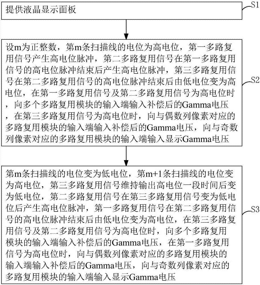
[0032] see image 3 , the invention provides a driving method of a liquid crystal display device, comprising the following steps:

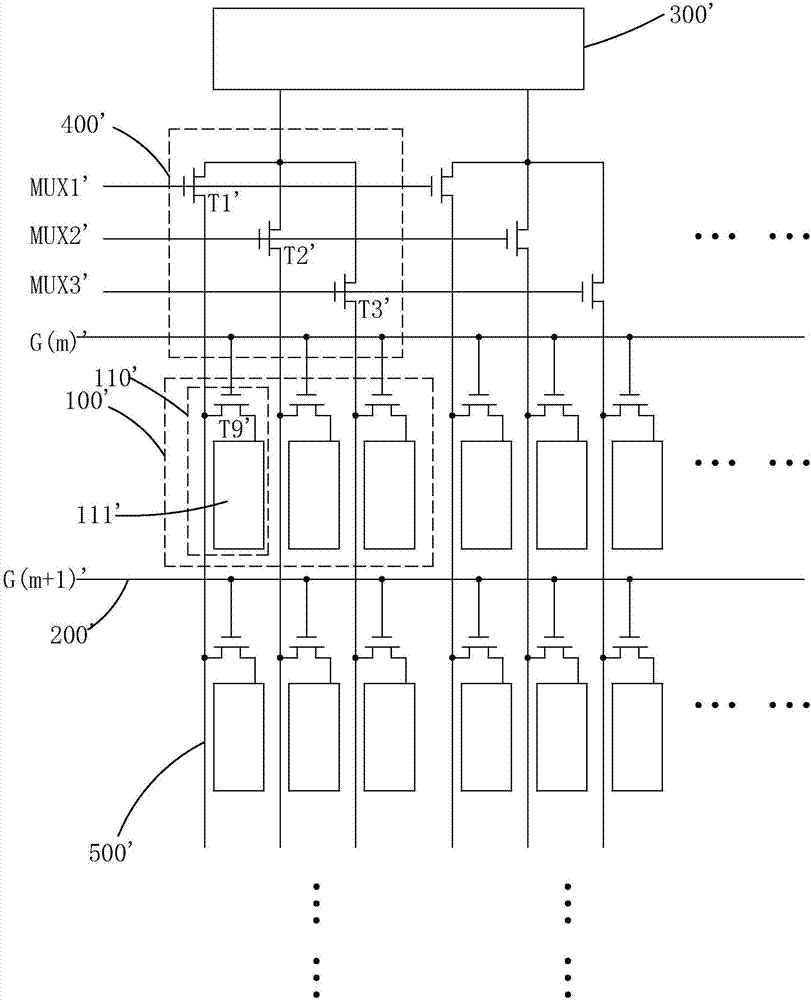
[0033] Step S1, please refer to Figure 4 , providing a liquid crystal display device.

[0034] The liquid crystal display device includes a plurality of pixels 100 arranged in an array, a plurality of scanning lines 200 corresponding to the plurality of rows of pixels 100, a plurality of multiplexing modules 400 corresponding to the plurality of columns of pixels 100, and a plurality of data lines 300; Each pixel 100 includes three sub-pixels 110 arranged in sequence, each sub-pixel 110 includes a switching thin film transistor T9, a pixel electrode 111 connected to the drain of the switching thin film transist...


PUM


Abstract

The invention provides a drive method of a liquid crystal display device. The drive method of the liquid crystal display device is characterized in that a first multi-path multiplexing signal, a second multi-path multiplexing signal and a third multi-path multiplexing signal control a first film transistor, a second film transistor and a third film transistor in a multi-path multiplexing module toopen at different moments successively when the m row pixel of the liquid crystal display device is driven by the method provided by the invention, compensated Gamma voltage is transmitted to sub pixels and even-row pixels connected with the first and the second film transistors as well as pixel electrodes of sub pixels connected with the third film transistor; Gamma voltage is transmitted to theodd-row pixels and the pixel electrodes of the sub pixels connected with the third film transistor, so that voltage drop generated by the pixel electrodes of the sub pixels due to the fact that the multi-path multiplexing signals are changed into low electric potential from high electric potential, and scanning lines are changed into low electric potential from high electric potential is compensated, and therefore, sub pixels are uniform in display brightness, and the liquid crystal display device is effectively prevented from flickering while displaying a picture.

Description

technical field [0001] The invention relates to the technical field of liquid crystal display, in particular to a driving method of a liquid crystal display device. Background technique [0002] A liquid crystal display (Liquid Crystal Display, LCD) includes a plurality of pixels arranged in an array, and each pixel usually includes sub-pixels of three colors: a red sub-pixel, a green sub-pixel and a blue sub-pixel, and each sub-pixel The pixels are all controlled by one scan line and one data line. The scan line is used to control the on and off of the sub-pixels. The data lines apply different data signal voltages to the sub-pixels to make the sub-pixels display different gray scales, thereby realizing full display in color. [0003] With the rapid development of LCD technology, people have higher and higher requirements for LCD clarity, that is, higher and higher resolution requirements for display panels; at the same time, due to the increase in resolution, more and mor...

Claims


Application Information

Patent Timeline
Patent Type & Authority Applications(China)
IPC IPC(8): G09G3/36
CPCG09G3/3607G09G3/3677G09G3/3696G09G2320/0233G09G2320/0276
Inventor 左清成袁小玲李曼
Owner WUHAN CHINA STAR OPTOELECTRONICS TECH CO LTD
Why Eureka
Try Eureka