Electric cable supporting device

A technology of supporting device and power cable, applied in the field of electric power, can solve the problems of pedestrian stumbling, prone to overturning, increased weight, etc., and achieve the effects of maintaining balance, convenient rotation and simple structure

Inactive Publication Date: 2018-05-04
YANCHENG POWER SUPPLY CO STATE GRID JIANGSU ELECTRIC POWER CO +4
View PDF1 Cites 0 Cited by
  • Summary
  • Abstract
  • Description
  • Claims
  • Application Information

AI Technical Summary

Problems solved by technology

Usually, the power lines are left scattered on the ground in the operation engineering, which makes the various power lines in a mess, which is not conducive to viewing and sorting the lines, and it is easy to cause pedestrians to stumble, or the power line leakage is caused by the wet ground. constitute a safety hazard
Therefore, in the process of operation, it is still necessary to temporarily erect and manage power lines. In view of this, there are currently some temporary erection supports for power lines that can support temporary power lines during construction or maintenance, but the current supports are only for The power lines are supported as a whole, that is, all the power lines are supported in strands, and the power lines cannot be supported according to actual needs, which is inconvenient for the classified construction or maintenance of power lines
[0003] The power line support proposed by the patent number CN202012670 includes a base, a support rod placed on a long screw above the base, and a plurality of fixing parts are threaded on the long screw rod, and the fixing parts include a threaded ring and a collar, and the threaded ring and the support The rod is threaded, and the power lines can pass through the collar for classified management and setting, which improves the safety and convenience of engineering operations, but in the case of more power cables, the number of fixed parts increases, but for a single vertically set For a long pole, it is bound to increase in weight, and the long pole is easy to lose balance and fall over, which will affect the classification construction and maintenance work of the power cable line in the later stage, and when moving the power line support, manual handling is required, and it is also easy to fall over during the handling process, and Time-consuming and labor-intensive, inconvenient to carry

Method used


Image

  • Electric cable supporting device
  • Electric cable supporting device

Examples


Embodiment Construction

[0022] In order to deepen the understanding of the present invention, the present invention will be further described below in conjunction with the embodiments and accompanying drawings. The embodiments are only used to explain the present invention and do not constitute a limitation to the protection scope of the present invention.

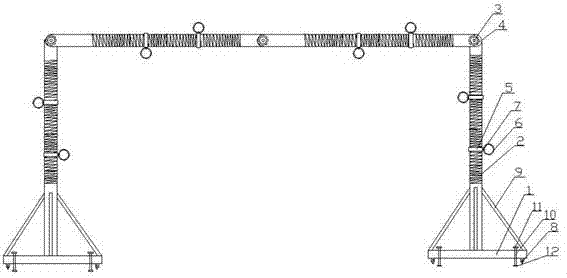
[0023] In this embodiment, a power cable support device, such as figure 1 shown, including

[0024] A base mechanism, the base mechanism includes a circular base 1 arranged on the left and right;

[0025] A support mechanism, the support mechanism includes four movably connected support rods 2, the support rods 2 on both sides are vertically arranged at the upper center position of the base 1, a rotating shaft 3 is arranged between adjacent two support rods 2, and adjacent The two support rods 2 rotate with the rotating shaft 3 as the hinge point, and the connection positions of the two adjacent support rods 2 are respectively provided with a pl...


PUM


Abstract

The invention discloses an electric cable supporting device which comprises a base mechanism, a supporting mechanism and a carrying mechanism. The base mechanism comprises a left circular base and a right circular base, the supporting mechanism comprises four movably connected supporting rods, the supporting rods positioned on two sides are vertically arranged at the centers of the upper portionsof the bases, a rotating shaft is arranged between two adjacent supporting rods, the connected positions of the two adjacent supporting rods are provided with a plurality of through holes, the throughholes in the two supporting rods sequentially and correspondingly formed, pins penetrate the two adjacent supporting rods, external threads are arranged on the outer end faces of the supporting rods,the carrying mechanism comprises a plurality of carriers placed on the supporting rods, the carriers comprise thread rings externally sleeving the supporting rods, internal threads in threaded connection with the supporting rods are arranged on the inner surfaces of the thread rings, and circular rings rotatably connected with the thread rings are arranged at outside ends of the thread rings. Theelectric cable supporting device has the advantages of simple structure, convenience in carrying and capabilities of supporting more cables and keeping balance.

Description

Technical field: [0001] The invention relates to the field of electric power, in particular to a power cable support device. Background technique: [0002] In engineering operations such as power grid construction and maintenance, many parallel power lines are often processed at the same time, such power lines include low-voltage transmission lines, cables, and optical cables (optical cables are not conductive, and the laying process of TV lines is similar to that of electric wires), etc. . Usually, the power lines are left scattered on the ground in the operation engineering, which makes the various power lines in a mess, which is not conducive to viewing and sorting the lines, and it is easy to cause pedestrians to stumble, or the power line leakage is caused by the wet ground. constitute a safety hazard. Therefore, in the process of operation, it is still necessary to temporarily erect and manage power lines. In view of this, there are currently some temporary erection ...

Claims


Application Information

Patent Timeline
Patent Type & Authority Applications(China)
IPC IPC(8): H02G1/06
CPCH02G1/06
Inventor 吉喆
Owner YANCHENG POWER SUPPLY CO STATE GRID JIANGSU ELECTRIC POWER CO
Why Eureka
Try Eureka