
Disinfection cabinet structure

A disinfection cabinet and air duct technology, applied in disinfection, sanitary equipment for toilets, dryers, etc., can solve the problems of aging and deterioration of items to be disinfected, affecting user experience, and high manufacturing cost of disinfection cabinets, so as to avoid aging problems. , the effect of shortening working time, saving energy and reducing consumption

Pending Publication Date: 2018-05-08
NINGBO FOTILE KITCHEN WARE CO LTD
View PDF0 Cites 8 Cited by
  • Summary
  • Abstract
  • Description
  • Claims
  • Application Information

AI Technical Summary

Problems solved by technology

[0003] Either way, the disinfection source generator is arranged in the liner in the existing disinfection cabinet, especially in the way of ultraviolet disinfection and / or ozone disinfection, and the ultraviolet rays will directly irradiate the materials and tableware inside the cabinet (especially the macromolecule material tableware), it will cause aging and deterioration of related parts and items to be sterilized in the liner, and even produce peculiar smell; it will not only affect the user experience, but will cause additional pollution sources in severe cases; and the disinfection process of the disinfection cabinet contains two stages, namely the disinfection stage and the drying stage, resulting in long working hours and high energy consumption
[0004] The high temperature disinfection is also because too high temperature will lead to rapid aging of the parts in the inner tank and the items to be sterilized. Therefore, there are strict requirements on the materials of the parts in the inner tank and the materials to be sterilized. High, and limits the application of disinfection cabinets

Method used


Image

  • Disinfection cabinet structure

Examples


Embodiment Construction

[0016] The present invention will be further described in detail below in conjunction with the accompanying drawings and embodiments.

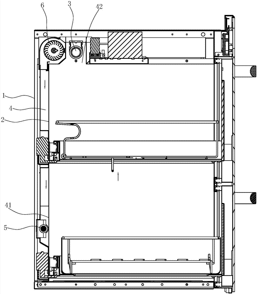
[0017] Such as figure 1 As shown, the disinfection cabinet structure includes:

[0018] The casing 1 is of a conventional structure and is a protective cover of the disinfection cabinet.

[0019] The liner 2 is sheathed in the shell 1 , and there is a gap between the liner 2 and the shell 1 .

[0020] The air duct 4 is arranged in the gap between the casing 1 and the inner tank 2 ; the air outlet 41 and the air inlet 42 of the air duct 4 are both connected to the inner cavity of the inner tank 2 . The design of the air duct 4 and the positions of the air outlet 41 and the air inlet 42 at both ends of the air duct 4 are good so that the air in the liner can smoothly circulate with the air duct; the air outlet 41 of the air duct 4 in the present embodiment Located at the lower part of the liner 2 close to the bottom surface of the liner, the ...


PUM


Abstract

The invention relates to a disinfection cabinet structure. The disinfection cabinet structure comprises a housing, and an inner container (2) and a disinfection source generator (3) which are arrangedin the housing (1); a wind channel (4) is arranged in a gap between the housing (1) and the inner container (2); a wind outlet (41) and a wind inlet (42) of the wind channel (4) are communicated withthe internal cavity of the inner container (2); a heating device (5) and a blower fan (6) are arranged in the wind channel (4); and the disinfection source generator (3) is arranged in the wind channel (4). The disinfection cabinet structure is capable of solving problems in the prior art; the disinfection source generator is arranged in the inner container; disinfection and heating processes arecombined; energy saving effect is excellent; aging problem caused by direct action of the disinfection source on the components and the articles to be disinfected in the inner container is solved; the disinfection cabinet structure is safe, is friendly to the environment, is good for health; requirements on materials of the components and the articles to be disinfected in the inner container arereduced greatly; application range is wider; no disinfection blind angle is left; and drying temperature is more uniform.

Description

technical field [0001] The invention relates to a disinfection cabinet structure. Background technique [0002] Existing disinfection cabinets generally include a shell, which is provided with an inner container, which is provided with a drawer for placing articles to be sterilized, and is also provided with a disinfection source generator capable of releasing sterilizing substances. The disinfection source generator is usually an ultraviolet lamp or an ozone generator, or a combination of the two; these methods need to be combined with a drying function to dry the tableware after disinfection; there are also direct high-temperature disinfection methods, Dry the items to be sterilized while sterilizing at high temperature. [0003] Either way, the disinfection source generator is arranged in the liner in the existing disinfection cabinet, especially in the way of ultraviolet disinfection and / or ozone disinfection, and the ultraviolet rays will directly irradiate the materia...

Claims


Application Information

Patent Timeline
IPC IPC(8): A61L2/06A61L2/26F26B21/00
CPCA61L2/06A61L2/26F26B21/001A61L2202/15
Inventor 陈松军茅忠群诸永定李斌
Owner NINGBO FOTILE KITCHEN WARE CO LTD
Learn More