
Automatic CCD detecting device

An automatic detection and equipment technology, applied in the field of automation, can solve problems such as high dependence on operators, confusion between good and defective products, and error-prone product screening.

Inactive Publication Date: 2018-05-08
东莞市罗思五金科技有限公司
View PDF5 Cites 1 Cited by
  • Summary
  • Abstract
  • Description
  • Claims
  • Application Information

AI Technical Summary

Problems solved by technology

[0002]With the continuous development of science and technology, large-scale automatic production requires fast, high-precision and automatic measurement of processed products. It is mainly manual sorting. Operators check each product with their eyes. The demand for personnel is large, and the efficiency of manual inspection operation is low, the labor intensity is high, and the dependence on operators is very high. When operators are replaced by old and new ones, or when operators use their eyes for a long time and cause visual fatigue, it is easy to make mistakes in product screening, resulting in missed inspection of unqualified products, causing confusion between good and defective products, and making the quality of the whole batch of products unsatisfactory. To guarantee, it will bury a deep quality hidden danger for the subsequent process
Therefore, a device that can automatically detect products should be designed to avoid the disadvantages of manual detection that are prone to errors, reduce labor costs, and improve product quality.

Method used


Image

  • Automatic CCD detecting device
  • Automatic CCD detecting device
  • Automatic CCD detecting device

Examples


Embodiment

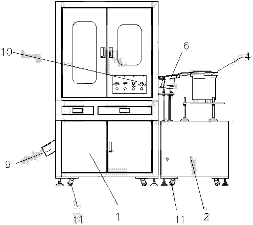
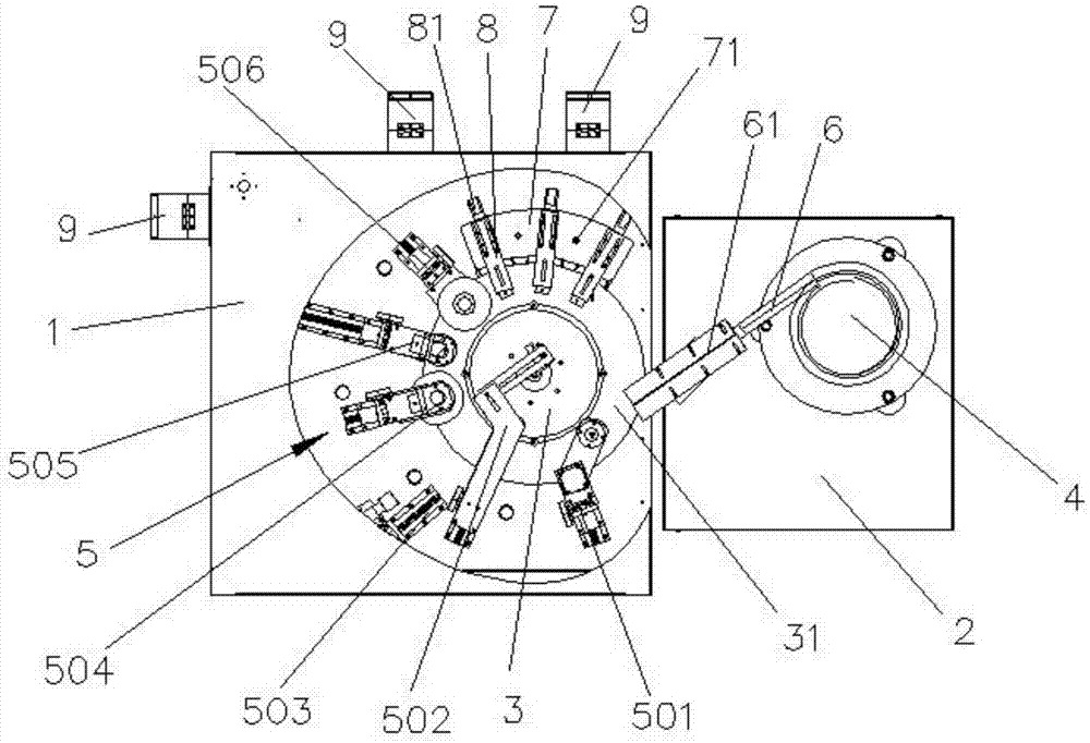
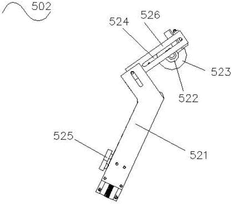
[0023] see Figure 1 to Figure 3 , a kind of CCD automatic detection equipment provided by the present invention, comprises equipment base 1, vibrating disc base 2, workbench turntable 3, vibrating disc 4, CCD detection device assembly, feeding trough 6 and discharge box 7, described workbench turntable 3 is set on the equipment base 1, the vibration plate 4 is set on the vibration plate base 2, the equipment base 1 and the vibration plate base 2 are juxtaposed, and the vibration plate 4 is connected to the worktable turntable 3 through the feeding groove 6 , the feeding chute 6 is tangent to the head end of the worktable turntable 3, the CCD detection device assembly is arranged on the equipment base 1, the CCD detection device assembly 5 includes at least four CCD detection devices, and the CCD detection device assembly 5 includes at least four CCD detection devices. The devices are irregularly distributed along the workbench turntable 3, the CCD detection device includes a ...


PUM


Abstract

The invention provides an automatic CCD detecting device comprising a device base, a vibrating disk base, a workbench rotating disk, a vibrating disk, a CCD detecting device assembly, a feeding grooveand a discharging groove. The workbench rotating disk is arranged on the device base. The vibrating disk is arranged on the vibrating disk base. The device base and the vibrating disk base are arranged side by side. The vibrating disk is connected with the workbench rotating disk through a feeding groove. The feeding groove is tangent to the head end of the workbench rotating disk. The CCD detecting device assembly is arranged on the device base. At least one CCD detecting device is provided with a 360-degree camera. The discharging box is arranged at the tail end of the workbench rotating disk. The upper portion of the discharging box is provided with at least one mechanical arm. The automatic CCD detecting device is provided with six CCD detecting devices, so that product detection automation is achieved, the possibility of detection missing or wrong detection caused by manual factors during manual detection is reduced, the detection efficiency and yield of products are improved, and manual cost is reduced.

Description

technical field [0001] The invention relates to the technical field of automation, in particular to a CCD automatic detection device. Background technique [0002] With the continuous development of science and technology, large-scale automatic production requires fast, high-precision and automatic measurement of processed products. In the past, the selection of good and defective products was mainly manual sorting. There is a large demand for personnel to check the products, and the efficiency of manual inspection operation is low, the labor intensity is high, and the dependence on operators is very high. When you are tired, it is easy to make mistakes in the screening of products, resulting in missed inspection of unqualified products, causing confusion between good products and defective products, making the quality of the entire batch of products not guaranteed, and burying deep quality hidden dangers for subsequent processes. Therefore, a device that can automatically ...

Claims


Application Information

Patent Timeline
IPC IPC(8): B07C5/00B07C5/02B07C5/36H04N5/225H04N5/247H04N5/372
CPCB07C5/00B07C5/02B07C5/362B07C2501/0063H04N23/54H04N23/50H04N23/55H04N23/90H04N25/71
Inventor 郭峰平
Owner 东莞市罗思五金科技有限公司
Learn More