Bicycle lock
A bicycle and car lock technology, which is applied in the direction of bicycle locks, bicycle accessories, bicycle brackets, etc., can solve the problems of "inadequate coverage, high site requirements, high construction investment costs, etc., to improve the image of the city and the degree of automation High, good anti-theft effect
- Summary
- Abstract
- Description
- Claims
- Application Information
AI Technical Summary
Problems solved by technology
Method used
Image
Examples
Embodiment 1
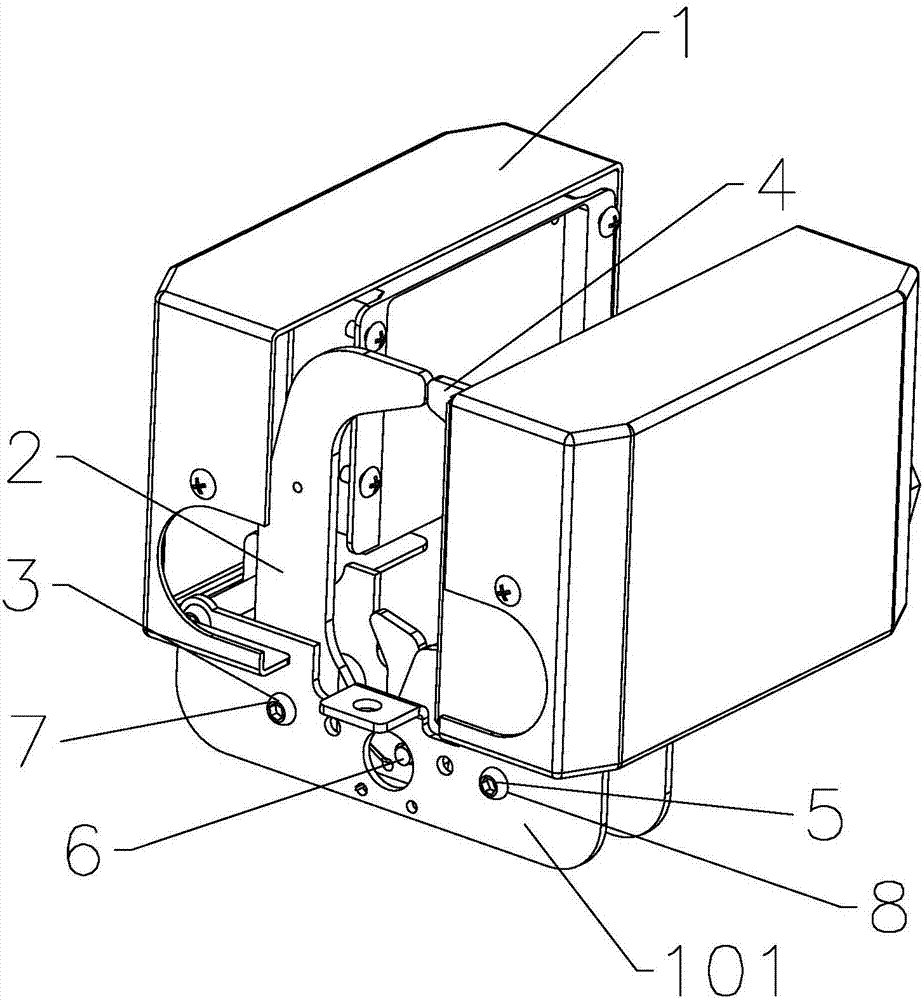
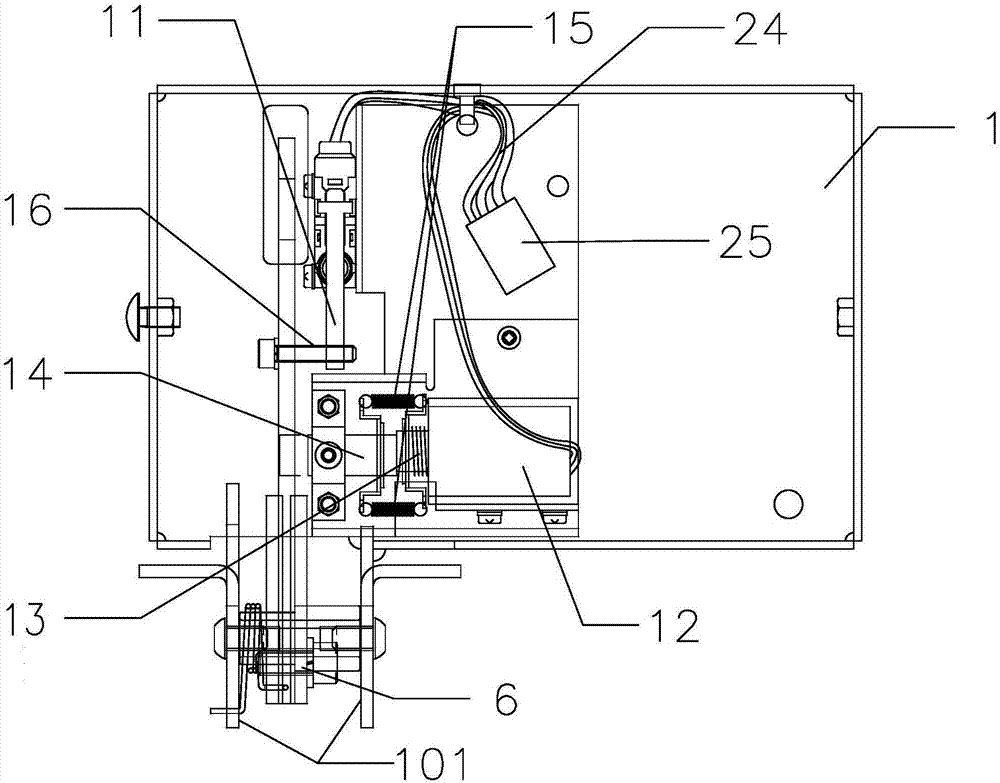
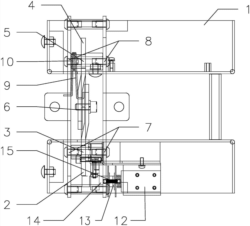
[0025] A kind of bicycle lock, comprises lock shell 1 and lock mechanism, as Figure 1-Figure 5 As shown, the lock housing 1 includes a lock housing bottom support 101, and the car locking mechanism is connected with the lock housing 1. The car locking mechanism includes a first lock hook 2, a first pin shaft 3, a second lock hook 4, a second pin shaft 5, Lock tongue pin shaft 6, first shaft hole 7 and second shaft hole 8 are arranged on the lock housing, first lock hook 2 can be divided into first lock arm 201 and first lock tongue 202 according to position, second lock hook 4 It can be divided into the second lock arm 401 and the second lock tongue 402 according to the position. The first lock hook 2 and the second lock hook 4 are connected by the lock tongue pin 6 at the positions of the first lock tongue 202 and the second lock tongue 402 , the first lock hook 2 is rotatably connected to the first shaft hole 7 of the lock case through the first pin shaft 3 at the position ...
Embodiment 2
[0030] Basically the same as embodiment 1, the difference is as Figure 7 As shown, the return spring 9 is an extension spring, one end of the extension spring is connected to the second lock hook 4 , and the other end of the extension spring is connected to the bottom bracket 101 of the lock case.
Embodiment 3
[0032] It is basically the same as Embodiment 1, the difference is that a limit switch 11 and an electromagnetic lock 12 are installed inside the lock housing 1, and the electromagnetic lock 12 and the limit switch 11 are connected through a drive connection line 24, and a limit switch is provided on the first lock hook 2. The position bolt 16, the limit bolt 16 is used to start the limit switch 11, after the first lock hook 2 and the second lock hook 4 rotate around the deadbolt pin shaft 6 to the closed state, and the drive module of the electromagnetic lock receives the locking signal , the shaft core 13 of the electromagnetic lock 12 abuts against the outer wall of the first lock hook 2 .
PUM
 Abstract
Description
Claims
Application Information
 - R&D
- Intellectual Property
- Life Sciences
- Materials
- Tech Scout
- Unparalleled Data Quality
- Higher Quality Content
- 60% Fewer Hallucinations
Browse by: Latest US Patents, China's latest patents, Technical Efficacy Thesaurus, Application Domain, Technology Topic, Popular Technical Reports.
© 2025 PatSnap. All rights reserved.Legal|Privacy policy|Modern Slavery Act Transparency Statement|Sitemap|About US| Contact US: help@patsnap.com


