

Adjustable keyboard
Patent Information
- Authority / Receiving Office
- CN · China
- Current Assignee / Owner
- 新昌县澄聚农业科技有限公司
- Publication Date
- 2018-05-08
Smart Images
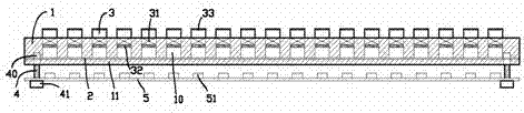
Figure 1 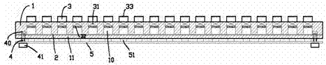
Figure 2 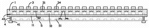
Figure 3
Abstract
Description
technical field
[0001] The invention relates to the field of computer accessories, in particular to a keyboard. Background technique
[0002] Due to the habits, preferences, and moods of each person, there are different requirements for the softness and hardness of the keyboard keys; and the hardness of the current keyboard keys is fixed, which limits the audience of a certain type of keyboard. , and cannot meet the actual needs of the same user in different scenarios. Contents of the invention
[0003] In view of the above problems, the purpose of the present invention is to provide an adjustable keyboard, which can flexibly adjust the softness and hardness of the keys when they are pressed during use, so as to meet the needs of different users and different scenarios.
[0004] The first technical solution adopted by the present invention to solve the technical problem is: the adjustable keyboard includes a base shell, the lower part of the base shell forms a support pla...