
Eureka
For R&D, Eureka makes reading and utilizing patents & technical documents easy.
Eureka AIR
Designed for self-driven R&D workflows. Generate viable solutions, solve complex R&D challenges, empower your innovation with AI.

Eureka Materials
Designed for material experts only. Revolutionize your material R&D, from search, analyze, to developing new materials.

TechResearch
Generate reliable direction feasibility study reports for your R&D in just a few steps.

TechSeek
Discover and master advanced knowledge NOW. Basics, ideas, possibilities, all at once.

TechMind
As an expert in R&D Theories, TechMind can generates customized viable solutions instantly.

TechRisk
Analyze your overall solution with one click, know your potential R&D risks in advance.

TechMonitor
Get weekly tech updates, stay abreast of the latest tech innovations and key insights.
Novel Wilkinson power divider capable of achieving termination with complex impedance
A technology of power divider and complex impedance, which is applied in the field of new Wilkinson power divider, can solve the problems of not having complex impedance transformation, etc., and achieve the effect of low difficulty in process realization, simple design and low power consumption
- Summary
- Abstract
- Description
- Claims
- Application Information
AI Technical Summary
Problems solved by technology
Method used
Image


Examples
Embodiment 1
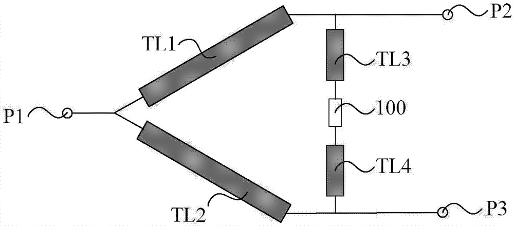
[0031] See figure 2 , figure 2 A schematic diagram of a circuit structure of a novel Wilkinson power divider capable of terminating complex impedances provided by an embodiment of the present invention, the power divider includes a first microstrip line TL1, a second microstrip line TL2, and a third microstrip line TL3, the fourth microstrip line TL4, the input end P1, the first output end P2, the second output end P3, and the isolation circuit 100, wherein,
[0032] The first microstrip line TL1 is connected in series between the input end P1 and the first output end P2; the second microstrip line TL2 is connected in series between the input end P1 and the second output end Between P3; the third microstrip line TL3, the isolation circuit 100, and the fourth microstrip line TL4 are serially connected between the first output end P2 and the second output end P3 in sequence.
[0033] The beneficial effects of the embodiments of the present invention are as follows:
[0034]...
Embodiment 2
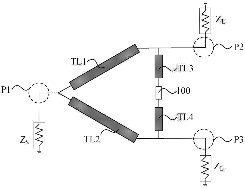
[0037] See image 3 , image 3 A schematic diagram of the circuit principle of a novel Wilkinson power divider capable of terminating complex impedances provided by an embodiment of the present invention. On the basis of the foregoing embodiment, this embodiment includes the entire contents of Embodiment 1, and focuses on the detailed description of the design method and specific structure of the Wilkinson power divider.
[0038] In an ideal loss-free condition, the impedance of the power divider of the embodiment of the present invention connected to the input end P1 is set to Z S ,Z S The value of satisfies the formula Z S =R S +jX S ; The impedance of the connection between the first output end P2 and the second output end P3 is both Z L ,Z L The value of satisfies the formula Z L =R L +jX L ; The characteristic impedances of the first microstrip line TL1 and the second microstrip line TL2 are both Z 1 , the electrical length is θ 1 ; The characteristic impedances...
Embodiment 3
[0071] This embodiment further describes the effect of the present invention in combination with a specific circuit design case on the basis of the above-mentioned embodiment.
[0072] See Figure 8 , Figure 8 A schematic diagram of the layout structure of a novel Wilkinson power divider capable of terminating complex impedances provided by an embodiment of the present invention. Using 0.25μm GaAs pHEMT process, a new Wilkinson power divider with a center frequency of 31GHz that can be terminated with complex impedances is designed. The power divider is a 3-dB structure. The impedance Z connected to the input port P1 S =55-j×40Ω, the impedance Z connected to the first output end P2 L =60-j×30Ω. According to these known conditions, combined with the above design formula, the first microstrip line TL1 and the second microstrip line TL2 are both 943 μm in length and 27.37 μm in width, and the third microstrip line TL3 The length of the fourth microstrip line TL4 and the leng...
PUM
| Property | Measurement | Unit |
|---|---|---|
| Resistance | aaaaa | aaaaa |
| Inductance value | aaaaa | aaaaa |
| Reflection coefficient | aaaaa | aaaaa |
Abstract
Description
Claims
Application Information
 - R&D Engineer
- R&D Manager
- IP Professional
- Industry Leading Data Capabilities
- Powerful AI technology
- Patent DNA Extraction
Browse by: Latest US Patents, China's latest patents, Technical Efficacy Thesaurus, Application Domain, Technology Topic, Popular Technical Reports.
© 2024 PatSnap. All rights reserved.Legal|Privacy policy|Modern Slavery Act Transparency Statement|Sitemap|About US| Contact US: help@patsnap.com