
Parallel compression spring type double-acting balance cylinder applied to industrial robots

An industrial robot and compression spring technology, applied in the field of robots, can solve the problem of one-way balance: the extension spring only works when the spring is tensioned; the compression spring only works when the spring is compressed, which is unfavorable for promotion and high cost. , to achieve the effect of simple and compact structure, wide applicability and low production cost

Active Publication Date: 2020-11-06
SHANGHAI AEROSPACE SYST ENG INST
View PDF9 Cites 0 Cited by
  • Summary
  • Abstract
  • Description
  • Claims
  • Application Information

AI Technical Summary

Problems solved by technology

The disadvantage is that the spring balance device is only one-way balanced: the tension spring only works when the spring is under tension; the compression spring only works when the spring is under compression
Limits the range of motion of the robot arm to some extent
[0005] Pneumatic or hydraulic balancing method refers to: through the pneumatic cylinder or hydraulic cylinder combined with specific valve action to achieve the balance of the robot arm, the disadvantage is that the reaction speed is slow, not suitable for high-speed industrial robots
[0006] The balanced torque motor method refers to the use of a balanced torque motor to achieve the balance of the robot arm. The disadvantage is that the cost is high and it is not conducive to popularization.

Method used


Image

  • Parallel compression spring type double-acting balance cylinder applied to industrial robots
  • Parallel compression spring type double-acting balance cylinder applied to industrial robots
  • Parallel compression spring type double-acting balance cylinder applied to industrial robots

Examples


Embodiment Construction

[0054] The present invention will be described in detail below in conjunction with specific embodiments. The following examples will help those skilled in the art to further understand the present invention, but do not limit the present invention in any form. It should be noted that those skilled in the art can make several changes and improvements without departing from the concept of the present invention. These all belong to the protection scope of the present invention.

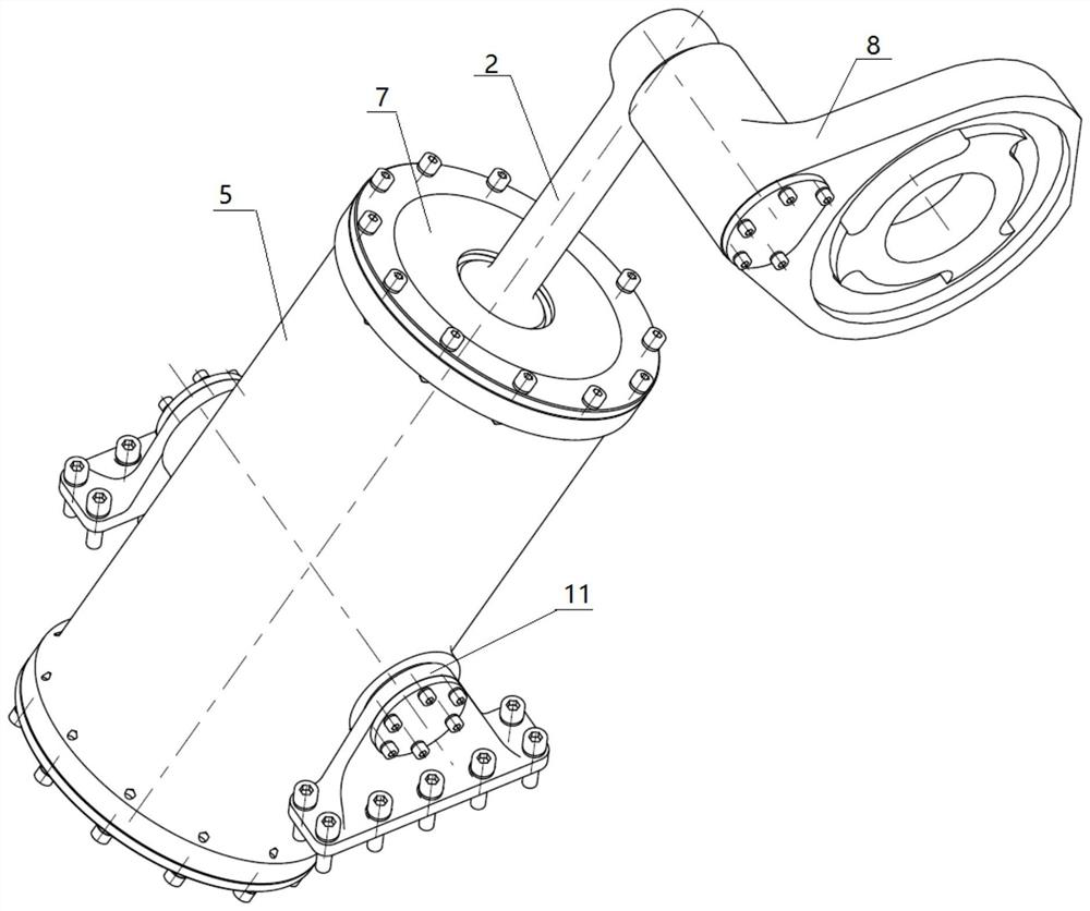
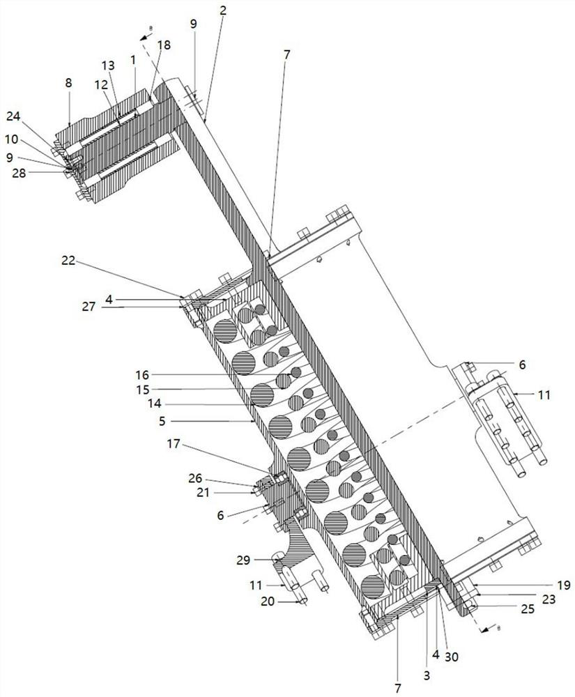
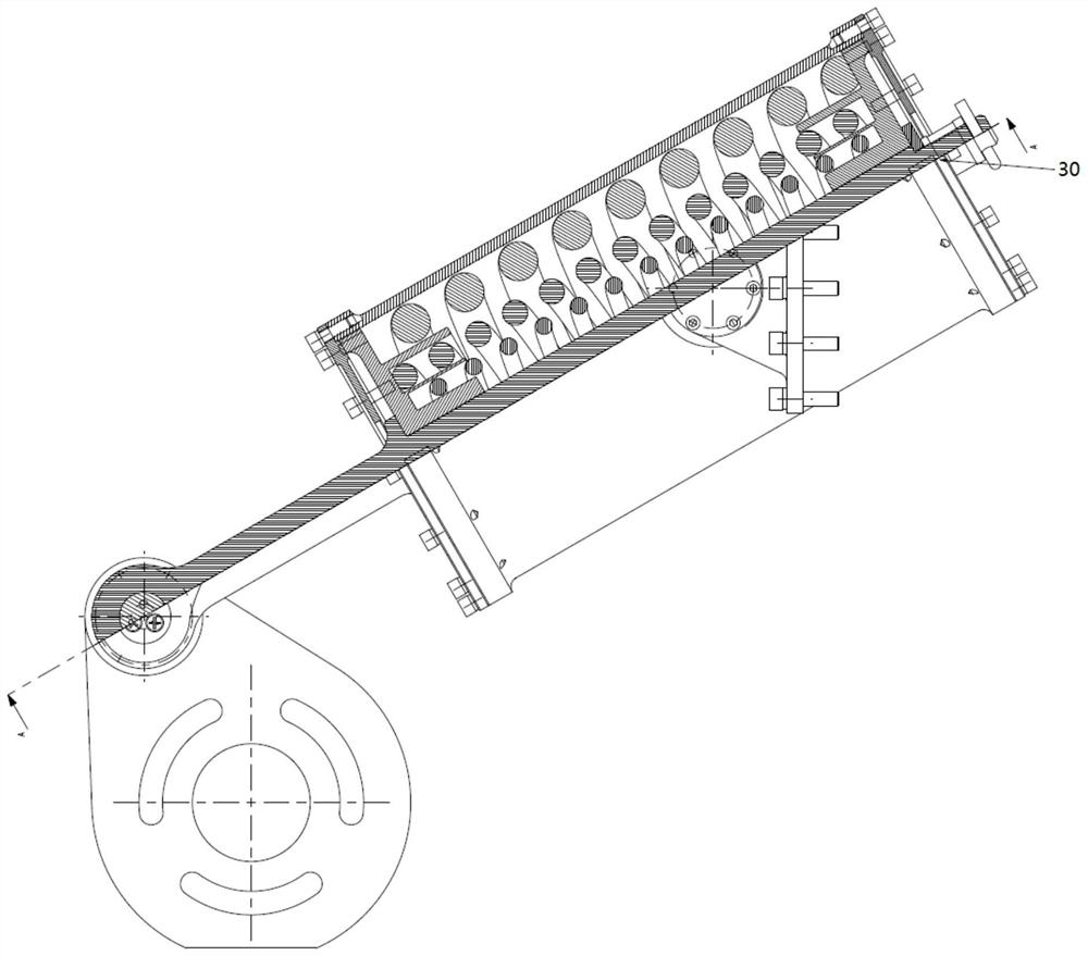
[0055] figure 1 A schematic diagram of the three-dimensional structure of the parallel compression spring type double-acting balance cylinder applied to the industrial robot provided by the present invention; figure 2 A schematic cross-sectional structure diagram of a parallel compression spring type double-acting balance cylinder applied to an industrial robot provided by the present invention; image 3 It is another schematic cross-sectional structure diagram of a parallel compression spring type do...


PUM


Abstract

The invention provides a parallel compression spring type double-action balance cylinder applied to an industrial robot. The balance cylinder comprises a handle shaft, a cylinder shaft, a cylinder body, a rocker arm, a cushion ring, pistons and at least one compression spring; the first end of the cylinder shaft is fixedly connected with one end of the handle shaft, and the second end of the cylinder shaft penetrates through a cylinder cover at the top end of the cylinder body to enter the cylinder body to be connected with the cushion ring, and penetrates out of a cylinder cover at the bottomend of the cylinder body; the pistons are arranged at the top end and the bottom end inside the cylinder body correspondingly, and at least one compression spring is arranged between the two pistonsinside the cylinder body; and the handle shaft is connected with the rocker arm through a connecting mechanism, and the rocker arm is connected with a large arm of the industrial robot. According to the balance cylinder, the movable cylinder body structure is arranged, and the double pistons are arranged in the cylinder body, so that the bidirectional balance operation of stretching or compressingof the balance cylinder is realized; and the balance cylinder is simple and compact in structure, low in manufacturing cost and is simple and easy to implement, the movement range of a arm rod of therobot is not limited, and the applicability is high.

Description

technical field [0001] The invention relates to the technical field of robots, in particular to a parallel compression spring type double-acting balance cylinder applied to industrial robots. Background technique [0002] In order to reduce the driving torque of the industrial robot and increase the motion balance of the robot, it is necessary to install a balance device on the robot's big arm, small arm and even the wrist connection mechanism. Considering the rationality and safety of the mechanical drive, the balance device of the robot also helps to reduce the dependence on the brake device when the power is suddenly cut off. Therefore, the balance device is very important to improve the overall performance and dynamic characteristics of the robot, and it is also an important measure to simplify programming and control. There are four common robot arm balancing techniques: mass balance method, spring balance method, pneumatic or hydraulic balance method, and balance torq...

Claims


Application Information

Patent Timeline
Patent Type & Authority Patents(China)
IPC IPC(8): B25J19/00F15B15/14F15B15/20
CPCB25J19/0012F15B15/1409F15B15/1428F15B15/20
Inventor 谢哲祁玮蒋松邵济明张晓伟王北江
Owner SHANGHAI AEROSPACE SYST ENG INST
Learn More