
Hydraulic lift type mortar transfer equipment

A transfer equipment, hydraulic lifting technology, used in containers, packaging, transportation and packaging, etc., can solve the problems of reducing the effect of receiving and discharging, unable to expand and contract, unable to lift and so on, to improve the receiving and discharging. effect, improve the sealing effect, the effect of good lifting stability

Inactive Publication Date: 2018-05-11
HUNAN MAINHORN TECH DEV CO LTD
View PDF0 Cites 3 Cited by
  • Summary
  • Abstract
  • Description
  • Claims
  • Application Information

AI Technical Summary

Problems solved by technology

[0002] In the prior art, the existing hydraulic lifting mortar transfer equipment cannot be lifted up and down when in use, resulting in the inability to seamlessly connect the mixer truck and the mortar delivery pump, thereby reducing the effect of receiving and discharging materials. The discharge device used in some hydraulic lifting mortar transfer equipment is usually a fixed structure, which cannot be stretched. It is necessary to transport the mortar delivery pump to the right below the discharge device, which increases the workload of personnel and improves the use effect. Low

Method used


Image

  • Hydraulic lift type mortar transfer equipment
  • Hydraulic lift type mortar transfer equipment

Examples


Embodiment approach

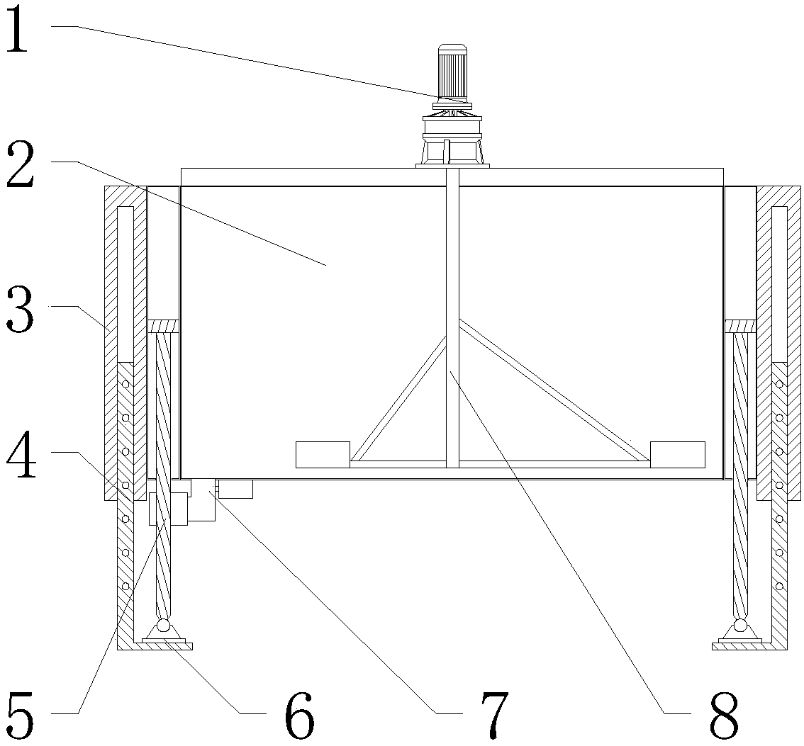
[0024] Specific implementation method: in actual use, the user starts the external oil pump, and the external oil pump works to flush the hydraulic oil into the hydraulic cylinder 5, thereby driving the hydraulic cylinder 5 to move upwards, and the hydraulic cylinder 5 moves upwards to drive the transfer tank 2 and casing 3 at the same time Move upward, when the intermediate tank 2 moves upward to a proper position, the user stops the external oil pump, and then the user holds the latch rod and inserts it into the latch hole on the mechanical leg 4 to support the casing 3. Then the user opens the mixer truck, the mixer truck works and pours the pre-mixed mortar into the transfer tank 2, and then the user starts the stirring motor 1, and the stirring motor 1 works to drive the stirring shaft 8 to rotate, and the stirring shaft 8 rotates to achieve stirring of the mortar. The design can be raised and lowered, and it is also convenient for mixing the mortar.

[0025] After the mo...


PUM


Abstract

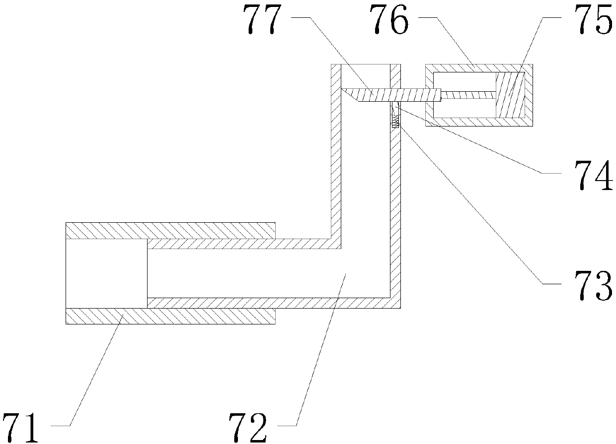
The invention provides hydraulic lift type mortar transfer equipment. The hydraulic lift type mortar transfer equipment comprises a transfer tank, sleeves, mechanical supporting legs, hydraulic oil cylinders, supporting leg base plates, a hollow pipeline, an L-shaped discharging pipeline, an electric push rod, a fixed tank body and a telescopic plate, wherein the hydraulic oil cylinders are separately installed at the outer ends of the transfer tank; each supporting leg base plate is arranged at the lower end of the corresponding hydraulic oil cylinder and is arranged at the internal bottom end of the corresponding mechanical supporting leg; and each sleeve is installed at the upper end of the corresponding mechanical supporting leg and is fixed to the outer end of the corresponding hydraulic oil cylinder. The hydraulic lift type mortar transfer equipment provided by the invention can implement a lifting action; the electric push rod is arranged at the right wall inside the tank body;the telescopic plate is arranged at the left end of the electric push rod and is installed on the L-shaped discharging pipeline; the hollow pipeline is installed at the left end of the L-shaped discharging pipeline; so the hydraulic lift type mortar transfer equipment can stretch and retract. The hydraulic lift type mortar transfer equipment provided by the invention is convenient to use and operate, can implement the lifting action, can stretch and retract, and is good in stability and high in reliability.

Description

technical field [0001] The invention is a hydraulic lifting type mortar transfer equipment, which belongs to the field of mortar transfer equipment. Background technique [0002] In the prior art, the existing hydraulic lifting mortar transfer equipment cannot be lifted up and down when in use, resulting in the inability to seamlessly connect the mixer truck and the mortar delivery pump, thereby reducing the effect of receiving and discharging materials. The discharge device used in some hydraulic lifting mortar transfer equipment is usually a fixed structure, which cannot be stretched. It is necessary to transport the mortar delivery pump to the right below the discharge device, which increases the workload of personnel and improves the use effect. Low. Contents of the invention [0003] Aiming at the deficiencies in the prior art, the purpose of the present invention is to provide a hydraulic lift type mortar transfer equipment to solve the problems raised in the above ...

Claims


Application Information

Patent Timeline
Patent Type & Authority Applications(China)
IPC IPC(8): B65D90/00B65D88/68
CPCB65D90/00B65D88/68
Inventor 蔡炳煌李仕林
Owner HUNAN MAINHORN TECH DEV CO LTD
Learn More